This mod is to basically develop PS4 Pro adapter plate, hardware and wiring adapters that are able to be transplanted between different PC cases with no modification to the actual PC case or PS4 motherboard.
REASONS
- Have a bigger style heatsink so that the PS4 APU runs cooler.
- Allow the motherboard exposure to more air rather than being in close proximity to a heated metal chassis.
- Motherboard steel chassis's rust and the rust particles fall on to the motherboard and can cause shorts.
- Easily replace the internal motherboard clock battery.
PERCENT COMPLETE
95%
TASKS
TASKS
Complete:
Create PS4 motherboard adapter plate
Create PS4 motherboard adapter plate
Prepare the APU heat sink
Create custom APU clamping hardware
Create a fan adapter cable
Create ATX power adapter cables
Create BT and WIFI Antenna PCI bracket
Find heat sinks for the APU Voltage Regulators
Find heat sinks for the RAM
Create PS4 to PC case LEDs adaptor
Create PS4 to PC case button adaptor
Build PC case rear IO connector plate
Create the Ethernet PCI bracket
Create the RAM heat sink Plate.
Not Complete:
Build the APU VRM heat sink mount.
Create fixed clamping hardware
Extras: (Not important so I might do later on)
Nickel-plate the RAM heatsink Plate.
PS4 MOTHERBOARD
Details:
The PS4 Pro motherboard measures about 240mm x 270mm and 1.4mm thick.
PS4 MOTHERBOARD
Details:
The PS4 Pro motherboard measures about 240mm x 270mm and 1.4mm thick.
There are currently 3 versions of PS4 Pro motherboard layouts. CUH-70xx that ship with NVA-00x motherboards. CUH-71xx that ship with NVB-00x motherboards. CUH-72xx that ship with NVB-00x motherboards. NVB and NVG motherboard versions have matching mounting hole locations. I will show you the differences in relation to NVA vs NVB\NVG motherboards.
As can be seen in the following pictures there are 4 differences highlighted in red circles. The three lower circles are new mounting holes that were not present on NVA motherboards. The highest red circle on is the standoff hole for NVB/NVG motherboards has been moved about 1mm on the horizontal plane in relation to the picture closer to the APU area. The following pictures show those differences.
PS4 CUH-70xx NVA motherboard pictured.

PS4 CUH-71xx NVB motherboard pictured.

ADAPTER PLATE
Details:
The PS4 motherboard is to be mounted on an aluminium adapter plate measuring 244mm x 270mm (micro-atx motherboard height). The purpose of the adapter plate is to combine the standoff holes from the PS4 motherboard and PC case motherboard standoffs onto the one plate.
PS4 CUH-70xx NVA motherboard pictured.

PS4 CUH-71xx NVB motherboard pictured.
ADAPTER PLATE
Details:
The PS4 motherboard is to be mounted on an aluminium adapter plate measuring 244mm x 270mm (micro-atx motherboard height). The purpose of the adapter plate is to combine the standoff holes from the PS4 motherboard and PC case motherboard standoffs onto the one plate.
Orientation:
The PS4 motherboard will be oriented so that the rear ports will be accessible through the PC case rear IO port area.
The PS4 motherboard will be oriented so that the rear ports will be accessible through the PC case rear IO port area.
Procedure:
I used the PS4 and PC motherboards as templates to drill the standoff adapter plate holes depending on the motherboard version. The basic process is as follows:
1. Clean the aluminium plate edges of any burs
2. Clamp the motherboard in place
3. Use a bench drill-press to lightly mark the standoff holes using the following drill sizes:
PC - 4mm
PS4 - 4mm - The holes around the APU
PS4 - 9/64 - Preferred, Otherwise use 3.5mm - All other mount holes
5. Remove the clamps and motherboard
6. Drill the marked holes all of the way through using the following drill sizes:
PC - 4mm
PS4 - 3mm
7. Remove the burs from the drill holes
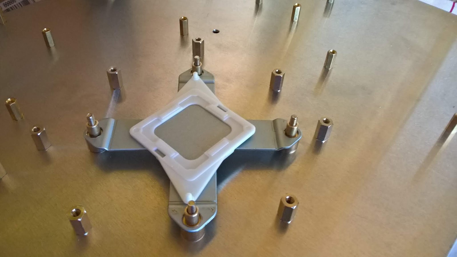
Drilling the Heatsink Clamping Hardware Holes:
To make sure the clamping bolts as close to centre as possibly on the aluminium adapter plate you can either:
Option 1 - Recommended
Create a custom spacer 6.5mm wide with a 3mm hole drilled through the centre. Place the spacer in each of the four motherboard clamping hardware through-holes before drilling a 3mm hole through the adapter plate.
NOTE: The 3mm drill hole in the middle of the 6.5mm spacer must be perfectly centred within the spacer.

Option 2 - Not Recommended
With the PS4 motherboard sitting on standoffs the shorter the better use a bench drill and a 6.5mm drill bit it is possible to drill straight down through each of the four motherboard heatsink clamping hardware holes. Use light pressure until the drill leaves a mark you can use a guide to drill all of the way through with a 3mm drill bit.
NOTE: ONLY USE IF you cannot make the spacers listed previously as this method is less accurate.
NOTE: If the drill grabs the motherboard clamping hardware hole it will widen out the hole making the centre mark less accurate.
NOTE: If the drill is bent it may result in out of place centre markings. The higher the standoffs the worse the issue can be.

Motherboard Adapter Plate.


Grinded PC motherboard.


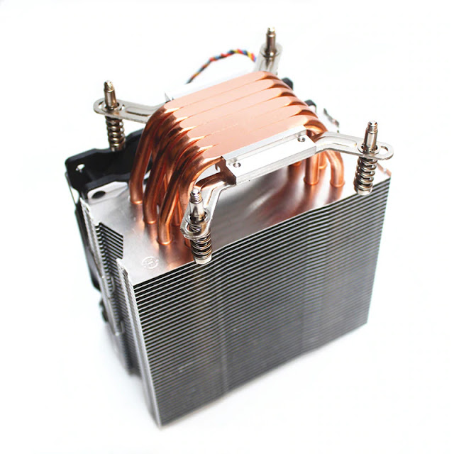
Modified Heatsink with shortened legs.

Motherboard Mounted.
HINT: If using an adapter plate measuring 305mm x 270mm (standard atx motherboard height) for the best results position the PS4 Pro motherboard so that the Ethernet port is directly behind the top PCI slot before drilling the standoff holes.
HINT: For the most accurate standoff hole locations in the adapter plate get faulty PS4 and PC motherboards. Then grind the motherboard bottom till all of the SMD components and protruding through hole component legs are gone and the motherboard bottom surface is flat.
WARNING: YOU SHOULD WEAR A FACE MASK TO STOP INHALING PARTICLES THAT MIGHT CAUSE INJURY OR ILLNESS.
Grinded PS4 Pro motherboard.

Grinded PC motherboard.

COOLING:
APU:
Due to the ability to easily adapt it to the PS4s clamp design I will be using either of the following.
Be Quiet! ShadowRock TF2 - Thanks to Firehuntah in the comments for linking to his project.

Or
Fujitsu-Siemens V26898-B854-V2.
Modified Heatsink with shortened legs.

Or
AliExpress heatsink.

Clamping
I have came up with custom clamping hardware that I can use for heatsink clamping.
For best results preferably buy the X-clamp from CUH-70xx PS4 Pros. Then bore the four holes out with a 1/4 drill. Connect the heat sink to the adapter plate using official x-clamp and created custom height spacers.
Order:
1. 3mm bolt
2. Adapter plate
3. Lower brass spacer. 3mm thread tapped through the centre. Use for all heatsink types. Height given is for 10mm PS4 motherboard standoffs.
2. Adapter plate
3. Lower brass spacer. 3mm thread tapped through the centre. Use for all heatsink types. Height given is for 10mm PS4 motherboard standoffs.
7.5mm (H) x 9mm (W).
4. Upper brass spacer. 3mm hole through the centre. This measurement of spacer is only for flat bottom heatsinks like the Fujitsu-Siemens V26898-B854-V2. Other heatsinks types where the processor contact area is at a different level to the clamping hardware will require a different length spacer.
6.75mm (H) x 6mm (W).
5. PS4 clamp and motherboard backing plate
6. Heat sink base legs / mounting hardware - Not Pictured
7. 3mm nut
Without Clamping hardware.

With clamping hardware.

Without Clamping hardware.

With clamping hardware.
WARNING: Care must be taken when inserting or removing the motherboard as it is more likely to flex when doing so, due to the spring state of the x-clamp. Proper procedure after placing the motherboard is to mount the heatsink. Then tighten the four heatsink nuts. Then screw the motherboard to the other adapter plate standoffs. Removing the motherboard should be done in the reverse order.
Hybrid Clamping:
I have also created hybrid clamping hardware for PS4 Pro using a mix of PS4 Pro and Xbox One FAT clamping hardware. I have done this for a few reasons. Firstly to avoid the other method (Above) which is more complicated due to the spring state of the PS4 x-clamp when securing the motherboard and heatsink. Also so that I can exchange heatsinks between my other Xbox PC case mods.
Parts:
- 4x Xbox One FAT green removeable heatsink. (not all are removable (green are)
- 1x Xbox One FAT x-clamp. Remove the centre plastic piece from it.
- 1x PS4 Pro APU clamp backing plate - Remove the centre metal piece from it. Break off the plastic clips that hold the metal piece in.
- 1x Steel plate - 37.5mm x 37.5mm x 1.5mm - Install the 1.5mm thick metal piece into the PS4 Pro APU clamp backing plate plastic part.
- 4x Brass Spacer - 5mm (H) x 10mm (W) - 2.5mm hole through the centre.
- 4x Brass Spacer - 3mm (H) x 6.5mm (W) - With a 3/16 hole through the centre.
Order:
- 2.5mm bolt ...mm in length
- Adapter plate
- Lower brass spacer - 5mm (H) x 10mm (W) with 2.5mm hole through the centre.
- PS4 Pro motherboard backing plate. Original steel 1mm thick plate piece replaced with same size steel plate but 1.6mm thick.
- Xbox 360 Winchester x-clamp with the centre plastic piece removed.
- Xbox 360 heatsink studs
- Upper brass spacer 3mm (H) x 6.5mm (W) - With a 3/16 (4.75mm) hole through the centre.
- PS4 Pro motherboard
- Heatsink
Fan:
Pinout: Top - Bottom, Same for all PS4 Pro motherboards.
Red - 12v
Black - GND
Blue - PWM (Speed)

I have made up a custom cable to allow the PS4 to run 4 pin PC fans. The PS4 does not have the fan RPM wire that typical PC fans have so I have left that pin unconnected as can be seen in the following picture.

RAM:
In order of preference.
1. Custom RAM Heatsink Plate:
I have decided to make custom RAM heatsink plate. Mine will be 135mm (Front USB to Rear ports) x 130mm x 1mm thick copper plate. I drilled the standoff holes. Marked the outline of the x-clamp and cut the x-clamp shape out of the plate. I will be DIY nickel plating the copper plate.
Mounting order:
- M3 bolt 20mm in length
- Motherboards Adapter Plate
- M3 standoff 6mm in height
- M3 washer 0.5mm in thickness. Used to spread out the compression force on the copper plate.
- Copper RAM heatsink 1mm in height. I now have a 1mm gap between the RAM modules surfaces. 1mm thermal pad or thermal putty will be used to sync them together.
- M3 nut 2.5mm in height.
Total height = 10mm. Same height as the PS4 motherboard standoffs.
RAM copper plate with official clamping hardware.

RAM copper plate with hybrid x-clamp hardware.

Use heat sinks on the RAM chips.

NOTE: Heat sinks mounted with double-sided thermal tape can and do fall off either due to low quality thermal tape and/or poorly cleaned RAM module surface before heat sink attachment.
NOTE: Heat sinks mounted with double-sided thermal tape can and do fall off either due to low quality thermal tape and/or poorly cleaned RAM module surface before heat sink attachment.
3. NVA EMI Shield
NVA motherboards you can use the RAM heat sink \ shield that came with that PS4 version. The RAM heat sink \ shield from NVA motherboards is not compatible with NVB\NVG motherboards due to a moved hole location and collisions with other surface mount components.
Because of the replacement custom clamping hardware I needed to drill 10+ mm (fixed in place way) holes in the RAM heat sink \ shield directly below the clamping bolt heads otherwise the standoffs would collide with the shield.

NVA motherboards you can use the RAM heat sink \ shield that came with that PS4 version. The RAM heat sink \ shield from NVA motherboards is not compatible with NVB\NVG motherboards due to a moved hole location and collisions with other surface mount components.
The thickness of the RAM shield is 0.5mm so that needs to be taken off of the 8 adapter plate standoffs around the APU area to make them the correct height.
Because of the replacement custom clamping hardware I needed to drill 10+ mm (fixed in place way) holes in the RAM heat sink \ shield directly below the clamping bolt heads otherwise the standoffs would collide with the shield.
NOTE: The 5th hole circled on the left side does not need to be modified. I did that earlier before finding out about the collision with components as mentioned above.
NOTE: Not Optimal because the design of the RAM heat sink \ shield traps the heat inside a cavity causing heating of the motherboard which intern raises the temperature of the APU because it is directly above in the center of the RAM chip area. Only use if you have no heat sinks to put on the RAM.
The PS4 motherboard has 6 APU voltage regulators each measuring 6mm x 6mm.
NVA Motherboards:
I'll probably just use Enzotech MOS-C1 heatsinks.

NVB/NVG Motherboards:
Either use Enzotech MOS-C1 heatsinks or use a single heatsink to cover all six six regulators.
To cover all of them with a single heatsink it needs to be at least 70mm in length and no wider then 6mm if using 1mm thermal pads due to surrounding surface mount components. A wider heatsink can be used with 1.5mm thick thermal pads to clear the surrounding surface mount components.
I will be creating a triangle cut-out of aluminium or acrylic (for the see-through look) that attaches to three standoffs that secure to the three motherboard mount holes surrounding the APU VRMs. Then I'll secure the heatsink to the triangle cut-out. The heatsink will then have thermal pad/s or thermal putty to transfer the heat.


NOTE: I am doing it this way as I don't want the heatsink to be able to detach.
Southbridge and Southbridge VRM:
To be added...PC CASE
Although my mod is not specific to an individual PC case I have chosen to use the Deepcool E-Shield or D-Shield.

POWERING:
See my other blog here for instructions on how to power the PS4 with a PC ATX power supply.


Made using a PC IO panel and adding a 1mm thick piece of aluminium with the PS4 rear ports cut out of it. Extremely hard to get it looking perfect so I did the best that I could.

PORTS
Depending on the PC case I will be able to use the following adapters to suit.
USB3 to USB3 PCI bracket.

USB3 Angle adapter.

USB3 to USB3 Pin header.

WiFi/BT:
I have designed a PCB to connect and extend the Wi-Fi antenna cables. Wifi cables will come from the motherboard to the PCB and from the antennas to the PCB. I have done it this way as attaching the Wi-Fi cables to the motherboard while the other end is still connected to the antennas makes it especially difficult connecting them.
I have mounted 3 antennas on a PCI blank bracket using U.FL to RP-SMA pigtails and RP-SMA antennas.


ETHERNET:
I have custom made a Ethernet bracket. I pulled the RJ45 port from an old laptop, cut the square hole out of a PCI bracket blank and soldered the port to the PCI bracket. I then soldered an 80cm Ethernet cable to the RJ45 port pins. This will be attached to one of the PCI slots.


NOTE: If you used an adapter plate measuring 305mm x 270mm the PS4 motherboard should be placed so that the Ethernet port is directly behind the top PCI slot. Cut a hole in a PCI blank bracket in the correct spot to make it look neat and proper.
Without PCI Bracket Blank.

With PCI Bracket Blank.

Without PCI Bracket Blank.
With PCI Bracket Blank.

DISC DRIVE:
Due to the size of the Blu ray drive in the PS4 it is not able to fit into the 5 1/4 inch drive bays. Also the disk drive circuit board is incorporated into the motherboard therefore it does not require the actual disc drive to be attached to launch games and apps unlike the earlier model FAT PS4s that do. It's coming to the end of the PS4s life cycle so I will be using PS4s without the disc drive as my PS4 Pro motherboard is jail-breakable so I no longer need the disc drive.
Stop the unrecognised disc icon from appearing:
Without the disc drive installed to stop the unrecognised disc icon from being shown on the PS4 menu you need to join two pins on the disc eject/detect ribbon cable connector. Do so either using an 8p ribbon cable to adapter PCB or by bridging pins 3 and 4 (3.3v) on the PS4 motherboard.
Motherboard connector pinout:
Pin Function
1 Sensor 1
2 Sensor 2
3 Sensor 3
4 3.3v
5&6 Eject Motor -/+
7&8 Eject Motor -/+
The way that I have done this is put a solder blob between two points on a cut down ribbon cable that I will insert into the PS4 motherboard connector. I have put the ribbon cable in upside down which still works as intended just so that I keep the solder blob from possibly shorting out on the motherboard.
Ribbon cable with solder blob joining the required two points.
BUTTONS:
Power Button:
The PS4 motherboard uses 6 pin 0.5mm pitch ribbon cable headers for these buttons. The two center pins are connected to the power button and the other four pins are GND. I have made the following adapter to suite the PC case buttons.

LIGHTS
The PS4 motherboard uses 6 pin 0.5mm pitch ribbon cable headers for these buttons. The two center pins are connected to the power button and the other four pins are GND. I have made the following adapter to suite the PC case buttons.
LIGHTS
Case LEDs:
The PS4 motherboard connects to LED PCBs through a 6 pin 0.5mm pitch ribbon cable. NVA motherboards use LED-001 PCB and NVB \ NVG motherboards use LED-002 PCB. They appear to be cross compatible with the other. The only difference I have noticed is the LED colour order \ location.
The PS4 case LED PCBs are supplied with 5 volts before going through a resistor. To use the PC case LEDs I need to have resistors on each circuit before the PS4 LED resistor on the PS4 side to protect the PC case LEDs.
PS4 LEDs to PC case LEDs:
- Blue - PS4 Blue LED
- White - PS4 White LED
- Green - Solder a 330 Ohm Resistor to the marked point on the side of the resistor and Connect to PC the front panel Power LED cable. Solder to the other point and connect to the PC front panel Power LED cable.
- Red - Solder a 330 Ohm Resistor to the marked point on the side of the resistor and Connect to the PC front panel HDD LED cable. Solder to the other point and connect to the PC front panel HDD LED cable.
LED-001 Side A PCB.


LED-002 Side A PCB.

PICS:
PS4 PRO: Old MicroATX Case.


CLEARANCE ISSUES
WHAT I STILL NEED TO KNOW
To be added as required.
MENTIONS
Id like to thank the following people for their input.
ozzylow - For giving me the idea to use aluminium motherboard adapter plates for all of my console to PC case mods.
CLEARANCE ISSUES
PS4 Pro:
1. The fan header is the highest object on the bottom of the motherboard at 6mm so you need at least that amount of clearance between motherboard and adapter plate.
2. The ram chips including their solder balls stick out from the motherboard about 1.5mm. Therefore I need to factor in their height as well as the height of the ram heat sinks I intend to use, which will intern give me the standoffs required height dimension.
Working out the heatsink clearance:
The height of the PS4 APU core above the PC case standoffs will be 1.6mm (adapter plate thickness) + 10mm (PS4 motherboard standoffs) + 1.4mm (PS4 motherboard) + 2.4mm (APU Core (H) above motherboard) = 15.4mm.
The height of the Intel CPU IHS top above the PC case standoffs is 1.5mm (PC motherboard) + 8mm (CPU IHS (H) above motherboard) = 9.50mm.
To find out if the chosen heatsink will still fit height wise into the PC case you must subtract 9.50mm (PC CPU core height) from 15.4mm (PS4 APU core height) = 6.4mm the PS4 APU core is higher than PC CPU core height.
Then take 6.4mm off of the PC case CPU heatsink clearance specification to get the maximum height value for the supported case heatsink clearance height specifications and choose a cooler height of that amount or less.
PC Case:
Since m-atx pc motherboards measure 245mm wide but the PS4 pro and adapter plate measure about 270 or so millimetres the PC case must have that extra bit of room at the front of the case. Also requires another few centimetres on top of that if you are going to be using USB angle changer adapters.
MEASUREMENTS
Just some PS4 Pro measurements that might help someone out.
- 2.4mm - Approximate height the APU core is above motherboard
- 2.35mm - Metal plate height for the i-clamp motherboard back plate
WHAT I STILL NEED TO KNOW
To be added as required.
MENTIONS
Id like to thank the following people for their input.
ozzylow - For giving me the idea to use aluminium motherboard adapter plates for all of my console to PC case mods.
ep-game-supply - Over on eBay - For getting me some parts.
JMAGG - Over on YouTube for his information on ribbon cables.
JMAGG - Over on YouTube for his information on ribbon cables.
FOR SALE
More Updates to follow...
Thanks so much for this guide. I finally have my PS4 PRO in a wooden case with custom cooling. No more crazy fan whine.
ReplyDeleteThanks for every other informative site. The place else may just I get that kind of information written in such an ideal means? I have a venture that I’m just now operating on, and I have been on the look out for such information. 5xv5k
DeleteFrom
ReplyDeletehttps://i.imgur.com/gUnbCfa.jpg
To
https://i.imgur.com/z5GCMWh.jpg
Interesting is that MDF (cardboard composite) or wood.
DeleteDo you have a write up anywhere out there on the net. I love seeing what others mods are like and the processes taken.
Its MDF with walnut veneer, I don't have much time to write something up but I am planning on making a video sometime.
ReplyDeleteThe hardest part was creating the CPU bracket, tried my hand at cutting acrylic and failed miserably. In the end had to get a CNC'ed one in aluminium done for me.
Another tricky part was finding out what those ribbon cables were actually called. I had googled for weeks and turned up nothing even using the part number printed on the cable itself. Everything was from China only and had huge lead times. It was only from a random search that I found your guide on PS3 hax. Your pin outs allowed me to buy the correct FPC connectors and rewire everything up.
https://i.imgur.com/vbbEFyH.jpg
Thank you Your guide has help me tremendously and I would like to show what I have done but still have a few questions
ReplyDeleteWhat questions do you want answered?
DeleteI have uploaded some pictures to Twitter you can go check him out there if you can @triggadafunz
ReplyDeleteBut my question was I continue to have overheating issues I have put thermal pads on Ram and voltage regulator have you had any heating issues ?
I myself don't believe I've had any heat related shutdowns but I am concerned about the ram temp feeling on touch. I've got an infra-red temp gun but due to the shiny copper surface I don't believe the readouts are accurate, the temp gun manual also states as much. I'm currently thinking about the best way to sink the ram directly to the support tray. My heat sinks are also glued on but I wouldn't recommend anyone glue unless you have no desire to reassemble PS4 at any point.
DeleteLooking on twitter I can only see what appears to be a liquid cooled PS4. Are you having overheating problems on that or do you have a PS4 PC case mod I didn't see? If so can you describe you ram heat transfer setup in a bit more detail as I can't quite picture it.
Here a link please let me know what you think
Deletehttps://imgur.com/gallery/9LoJFUY
This type of modification is difficult to judge. At the beginning, I also thought about modding like you did, but I decided against it for the following reasons. When the fan rotates, it draws air from the sides of the circuit board, cools the circuit board and then discharges the warm air via the power supply. If you drill a 6-hole hole in the housing, the complete airflow of the console changes and certain areas of the console may no longer be cooled as intended. It can still work, but if certain chips run at maximum performance or heat, they reduce the service life in the worst case Kind regards
DeleteHere a link please let me know what you think
ReplyDeletehttps://imgur.com/gallery/9LoJFUY
Looks sweet. Sorry it took so long to get back to you as I haven't been back here in a about a month.
DeletePS4 PRO's integrated water cooling I should buy a water-cooled head that supports the model motherboard.
ReplyDeleteThat's up to you. The PROs heat sink mounting holes at their centres are an even 60mm x 60mm apart so the liquid block must be able to be adjusted\adapted to suit those dimensions.
DeleteHello,
ReplyDeleteI'd like to thank you for sharing this project, it's really detailed and looks pretty good as well. Your build and also Kysen100's build really motivated me to start my own project. Just like Kysen100 I went with a custom wooden case. I just tried to keep everything as original as possible, so I needed no ribbon cable extensions or rewiring to different power buttons etc. I just used the original power and eject buttons. Only the LED I had to improvise a bit and ended up using an optical audio cable to extend the light and not the ribbon cable. The case is also as small as it can possibly be, all the components are really snug in there. As for the cooler I went with a Be Quiet! ShadowRock TF2, perfect match for the PS4 Pro in my opinion since it covers a large part of the motherboard. Just had to make my own mounting brackets as well. I'd say the result is really great, it's near silent and temperatures seem to be pretty stable.
Here are 2 quick pictures to see the result.
https://imgur.com/CCNR7Sq
https://imgur.com/V8sVs1t
And if you're interested, this is my full album.
https://imgur.com/a/vBllkPT
Also made a video with sound comparison at the end, such a difference with that original loud fan.
https://www.youtube.com/watch?v=AlMmrlSsWEM
Great Job. Really love being able to see the entire mod from start to finish.
DeleteAs for the air pressure inside of the case I assume the power supply is the main exhaust for the air all except a few small slits for the light bar, disc drive, USB and the rear I/O ports. Therefore the power supply fan needs to be able to exhaust at least but preferably more than the amount of air that enters the case.
Thanks! :) Made a lot of pictures of the project, thought it'd be nice to share as well for the people who want to do this as well.
DeleteYep that's true, the power supply has the only exhaust fan. And indeed there is some air leaking through all of the ports and even the cutout for the blu-ray drive as well, this is kind of reducing the air pressure a bit but I think it's fine.
What you're saying however with the exhaust needing to move at least the same amount of air as the intake I don't really agree with though. If the intake is the same as the exhaust there's actually no air pressure at all, just movement of air. You create air pressure by having a smaller exhaust than intake, this way the intake fan will push the air through the case and out of it through the exhaust fan and other openings. Other way around should work as well I guess, bigger exhaust than intake. But then it'll just suck more air into the case through all of the openings. Both I think are good but I'm more used to the bigger intake. I'm using the same for my PC that I used for gaming a few years ago, 2 intake fans and only 1 exhaust fan. And power supply being closed off from the case but having it's own intake and exhaust. Been able to game on that with very low temperatures and also pretty silent. That's why I decided to go this way with the PS4 Pro as well. The intake fan is 135mm and the exhaust fan in the power supply is 80mm. When you feel the air coming out of the back it feels like a much bigger fan is pushing that air out of the case. So that means there's definately some air pressure in the case.
I don't know if you'll ever see this see as this was two years ago but encase you do and you still have this mod.
DeletePlease add another 12 volt and GND wire to the main power prongs.
This will make it electrically safe as each atx pin no matter the connector (except the old IDE style power connector) is only safely capable of carrying 6 amps or 75 watts at 12 volts. The PS4 Pro can draw up to 180 watts or 15 amps.
Take the extra wires from the ATX PCIe or CPU auxiliary power connectors. For this you can buy connectors that plug into the those connectors on eBay or AliExpress for a few dollars.
Bit late but I did still end up seeing this. 😅 Thanks for sharing this info. Definitely would've modified it like that if I'd seen it earlier. Right now it's not in use anymore though due to upgrading to PS5.
DeleteIt is still working perfectly fine without any issues. I'm guessing there was enough cooling present inside the case to cool down the wires as well as usually drawing that much more current than intended does cause some thermal issues. While I did have it shut down a couple of times with overheating notification while playing heavy games (RDR2 for example) in the 4 years I've used it there were no issues at all.
Thankfully the PS5 is even more quiet than my modded PS4 Pro so no mods necessary for that one. 😋 Would still like to thank you for all the info you shared which made me mod my own one. Gaming experience was just so much better with the fan noise being nearly gone.
The two pins of the motherboard power supply can be modified to power the transformer to the motherboard.
ReplyDeleteHow can you convert 3PIN PWM fan to 4Pin PWM for compability to PC's Fan.
ReplyDeleteThe PS4 does not have the fan RPM wire.
DeleteThank you. Can you share the fan pin diagram or connecting guide.
ReplyDeleteWhere can i buy U.FL to RP-SMA pigtails and RP-SMA antennas?please help
ReplyDeleteGot mine on ebay.
DeleteThe original power supply is the transformer installed on the two long pins of the motherboard. If I want to change the transformer separately, what accessories do I have to buy?
ReplyDeleteOr whether the motherboard power supply is small or not, whether the positive and negative poles are suitable.
DeleteCan I sell the already connected ps4 pro24pin line? I hope you can sell it to me. Email a1835536224@gmail.com
ReplyDeleteSorry unfortunately I only ever built the one.
DeleteNeed a little money to make it and sell it to me.
DeleteThank you. Your post was the inspiration I needed to finish my own PS4 Pro silent mod: https://imgur.com/gallery/GjUa6kB
ReplyDeleteBeen away for a while and decided to check-in only to see your awesome mod. Congratulations.
DeleteThanks. I'm really happy with the mod and the skeleton look of it.
ReplyDeleteIf I will ever make another one, I might add a few RGB LEDs :-)
Well maybe with the PS5 next year, or if some pays me to do another PS4 Pro mod...
Need to sell more money, a ps4 pro 24pin and 12v power supply system is sold to me
DeleteHey, Finalman! I don't know if you'll see this but I was looking into trying my hand at a modded PS4. I'm not very experienced, so I was wondering if you sold any of those custom parts.
ReplyDeleteIf you interested to see how my casemod looks like:
ReplyDeletehttps://builds.gg/kufnukem/ps4-ultra-watercooled-22206
https://youtu.be/kAvR2D3eqbU
I love a great case mod as well as seeing the how it all came together. Congratulations.
DeleteI'd love to do a custom water loop myself since I've never done one but I mainly only have jailbroken systems and I'm not game enough to even try on those.
Is yours jailbroken or are you digital downloads only for now? Do you plan on adding the BD drive back at ay stage?
Would love to get a CNC machine for myself at some point.
Thank you was a really great project! I had a lot of fun doing it.
ReplyDeleteNo it’s not jailbroken just a regular one. The original plan was to include the BluRay but it did not fit into the case. I may review this in future. I may move the HDD to the front and try to fit the BD in the back. But for this the case is a lil bit small. Probably I would need to swap to the Core P5 and start all over.
The water cooling is almost no risk of your using good components. When using distilled water or premix coolants there won’t be any damage on a leak. Another Idea was to use a AIO for cooling. But in my case the custom loop just looked way better.
Hello,how can i found the version of motherboard?
ReplyDeleteCUH....
It'll be written on the motherboard. It'll start with either NVA-00x, NVB-00x or NVG-00x.
DeleteCUH-70xx's come with NVA-00x.
CUH-71xx's come with NVB-00x.
CUH-72xx's come with NVG-00x.
Hello Finalman, I were looking on Google with no result for alternate pinpoint for Power Supply Connector, I ripped off when trying to change the button battery. All four pinout ripped off, my console is a CUH-71xx model, Can you help me finding them? And in advance, thank you!
ReplyDeleteSee my other blog for underside motherboard solder points.
Deletehttps://finalmans.blogspot.com/2018/05/powering-ps4-with-pc-atx-power-supply.html
Hello! I'm wondering; if you power a ps4 with an ATX psu, how does rest mode work? Is the psu kept on (along with any case fans)?
ReplyDeleteYes rest mode works as normal and yes any case fans directly connected to the PC power supply continue to run.
DeleteI would like to thank you for your work on this guide. It was extremely helpful Here is my completed build.
Deletehttps://imgur.com/a/hkbyDvS
Hello! I know this is kind of off topic but I was wondering which blog platform are you using for this site? I'm getting fed up of Wordpress because I've had problems with hackers and I'm looking at options for another platform. I would be great if you could point me in the direction of a good platform.
ReplyDeletePs4 accounts for sale
Hey! This post could not be written any better! Reading this post reminds me of my previous room mate! He always kept chatting about this. I will forward this page to him. Fairly certain he will have a good read. Thank you for sharing!
ReplyDeletePs4 games on sale
Hello man I just wanna say thank you for doing this it inspired me to build something myself which brings me to my question I bought a pc tower from Amazon for about 100 buck I bought a water cooler kit for about 120 bucks what kind of a power supply do u recommend would a 500watt power supply be enough u see what im doing is basically taking apart my ps4 and just adding it to the pc tower along with a water cooler kit of course but I cant figure out the power supply I mean should I use the power supply that comes with the ps4 and modify the fans to power supply i mean the ps4 slim power supply is 250watts wouls it be able to power the fans and leds on the tower or wud the 500 watt power supply fry my ps4 motherboard
ReplyDeleteplz email at jrzy88@gmail.com im really stuck on this issue
DeleteRecommend you use a 500 watt PC bronze standard power supply at a minimum but if price is a concern you can use the PS4 one. You'll need to do alot of modifications for cooling and power cable extensions.
Deletenice post . cool pc cases
ReplyDeleteJust saw the same issue. Changing to a different power supply the issue disappeared.
ReplyDeleteI found out the issue with the power supply I was testing with was because it was a dual rail power supply.
ReplyDeleteCould you explain more how to wire the pc case power button to the ps4 pro? Thanks!
ReplyDeleteThe PS4 power on connector has 6 legs. The two inner are power On and the four outer, two either side of them are GND. Connect one wire coming from the PC case On switch to any GND point on the PS4 motherboard. Then the other wire coming from the PC case On switch to one or both of the two centre pins on the PS4 motherboard connector.
DeleteI myself picked up the pictured circuit board on eBay. Using it does not require soldering to the PS4 motherboard.
DeleteThanks, I got it to work as you did. How can I get the power led on the case button to work? Thanks
DeleteIt's more simple then it seems but here are the basics.
ReplyDeleteDe-solder 2.54mm jumper headers from old PC motherboards. Solder some wire onto one leg. On the other leg solder your resistor, see below. On the wire attached to the leg solder the wire the furthest side of the led that has a resistor connecting to it on the PS4 led board. Solder another wire to the resistor powering the led on the side furthest from the led. Then solder the wire attached to the PS4 board resistor to the resistor on the 2.54 header jumper. Plug into PC led connector.
2.54 connecter soldered resistor value depends on the supply voltage 5V at the far side of the PS4 led resistor.
I'll get back to you later with the resistor to use later.
DeleteAfter a quick look you should be safe with:
DeleteGreen PWR LED - 270 Ohm @10mA
Red HDD LED - 330 Ohm @10mA
Thanks for this info. Any chance you could post some more pictures? I think I understand however I’m having trouble determining the exact connections.
DeleteAdded pictures to the blog.
DeleteHi@all, Hi Finalman,
ReplyDeletei need your help, i converted my ps4 pro in a ATX HTPC Case and want to replace the original PS4 Pro PSU with a ATX PSU.
I buyed these Parts for this Project:
2N 4401 Bipolartransistor, NPN, 40V, 0,6A, 0,25W, TO-92
Link: https://www.reichelt.de/bipolartransistor-npn-40v-0-6a-0-25w-to-92-2n-4401-p219074.html?&nbc=1
MOLEX 39281243 Molex Stiftleiste - Mini-Fit Jr - 2x12-polig - Stecker
Link: https://www.reichelt.de/molex-stiftleiste-mini-fit-jr-2x12-polig-stecker-molex-39281243-p236824.html?&nbc=1
10 kOhm 1/4W
Link: https://atr-shop.de/elektronik-teile/widerstaende/metallfilmwiderstaende-14w-toleranz-1/962/10-kohm-1/4w-10-stck
My PS4 Pro Board is a NVA-001 - CUH-7xxx Series.
I make a Diagram but i dont know its correctly, can anyone if this correct me a answer to this ?
Diagram Link (Reddit):
https://preview.redd.it/z8opeqnj3qt61.png?width=3524&format=png&auto=webp&s=e6eea6b7eb031367bb0f661812fb4b3ba2d5c0b3
Article (Reddit) Link:
https://www.reddit.com/r/PS4Mods/comments/mspefq/ps4_pro_nva001_series_atx_psu_diagramm_correctly/
Best regards from Germany
The transistor collector (C) goes to ATX PWR ON and emitter (E) goes to ATX GND.
DeleteYou need to use at least three 12v rails and three GND rails. The two pairs from the ATX 24pin connector cannot safely supply the required current (amps) for the PS4 Pro.
See my BlogSpot tutorial here:
https://finalmans.blogspot.com/2018/05/powering-ps4-with-pc-atx-power-supply.html
Hello Finalman, thanks for your support.
ReplyDeleteI remake the diagram and hope it is correctly now, can you double ceck it ?
Dont want crash my PS4 ;-)
https://preview.redd.it/plw1oj05b3u61.png?width=1113&format=png&auto=webp&s=baf1fe493a590782f08f7e13936fd4aa0b6682bf
Hi Finalman,
ReplyDeleteI guess I’m a little confused on your PS4-ATX converter after reading this and you’re powering PS4 blogs. It looks like you wired the 4-pin straight to the 20-pin with no Optocoupler but with your PS4-ATX that is fix. If I wire my PS4 motherboard straight to the power block, will it fry it? Are there any alternatives to your custom PS4-ATX? Would you be willing to share your PCB blueprints, so I could order one online?
Thank you for this blog it’s great. I’m excited to start this project and just wanted to make sure every is good to go. It’s going to be my final project for one of my computer Science classes. If email is better your can reach me at lebreic@gmail.com
Thanks again
I'm powering mine using the pictured ATX adapter PCB with an optocoupler incorporated. You don't need a PCB as the circuit is very simple.
DeleteI mention the workaround method (bridging ATX PS_ON and GND) in the ATX powering blog purely for people who do not have a optocoupler/resistor/transistor.
As for my PCB it's only the first version I made up and I've already made a few adjustments to my design. In saying that my v1 is perfectly usable and I may sell them off as I got a heap left over. But probably the PCB only without components.
If you over volt a rail you will probably kill component/s or even the whole board. Meaning don't connect 12v to a 5v rail or connect voltage to a signal rail (ACDC_STBY).
Basically just make sure the wires go to where they're suppose to go before connecting it to the mains power.
Hey finalman,
ReplyDeleteSystem has been running great for a few months, but lately I’m having some issues with the power randomly cutting out and I would appreciate your opinion. I have the full setup with the transistor/resistor in a custom pc case, with the small chip to allow the pc case button to turn it on as well. Curiously, this isn’t the first time I’ve encountered random power cuts - when I first built it, it occurred as well, however I resoldered the two power cable wires and that seemed to fix it for a few months (0 power outs until recently). Now, however, the system can run anywhere from a few minutes to a few hours before cutting out.
Specifically, here is exactly what happens on power out:
The system loses power.
The ps4 controller does nothing when pressing the ps button (won’t start system).
The case button however does work, giving me a beep immediately when I press it.
Pressing the case button then a second time (or the ps4 controller) then works to turn it on.
The system then does the standard disk check due to a sudden power out, reboots, and loads back into the system fine.
System eventually cuts out again.
Could this perhaps be the power supply not consistently delivering power? I did not get a bronze rated psu, however I did get a name brand evga (450w, iirc). It seems odd to me that this would be again a cabling issue, as I took great lengths to solder the wires with care, and each individual wire is wrapped with shrink wrap to avoid any shorts. I repurposed the original power cable to the motherboard, as well as the 2 prong connector from the stock psu, so I believe those connections are fine. Perhaps the transistor/resistors I bought are now faulty? Forgive my ignorance, but my lack of experience with these electronics is hindering my ability to properly diagnose without replacing all the wires.
Thanks again for the help - your hard work here has let many of us undertake a fun project that would have otherwise not been possible, and I really appreciate that. Maybe add a wallet address for us to send some crypto your way as thanks? Just a thought!
Obviously we need to find out if anything is faulty either the transistor, resistor, PS4 motherboard or Power supply. I wouldn't expect the resistor to go bad but it's probably not impossible.
DeleteI'd probably troubleshoot in the following order:
1. Replacing both the transistor and resistor
2. Try using the power supply in a pc for a few hours
3. Try using a different pc power supply
4. Try to wire the PS4 power supply or reassemble the PS4 to test.
Just checking but you are not running a jailbroken PS4 are you?
I ask this as the exploits are always being tweaked so unforeseen issues may arise.
I would love to get this project to the point where the IO covers and adapter plate are 3d printable stls
ReplyDeleteDoes a ps4 turn on with any power supply
ReplyDeleteHello Finalman, I have followed your project to be able to adapt an atx and now I would like to be able to replace the heatsink because the original turbine makes a tremendous noise. Could you send me some photos of the adaptation process of this and its final assembly?
ReplyDeleteI bought a damaged and abused PS4 pro and I was able to turn it on with the atx, also the hdd was damaged and I installed a 3'5 hdd, I removed the reader, I assembled a pwm controller to manage the fan with a potentiometer and all this is mounted on a methacrylate but to maintain a temperature of 50 degrees the sound continues to be horrible, I would appreciate it if you would give me a hand.
By the way, turning on the atx I solved it with a 5v relay from arduino. Greetings and thank you.
I've away for a a few months and have only just checked back-in.
DeleteTake a look at this persons (Firehuntah) build here:
https://imgur.com/a/vBllkPT
I had decided to change my design to use the same heatsink. I got the mounting adapter hardware for the heatsink mostly complete but then got occupied doing other stuff.
I'll add some pics in a few days of my heatsink adapter hardware.
DeleteSorry I'm over a month and half too late with my reply.
Sorry never actually added pics but mine are very similar being rectangular in shape but are made out of 2.5mm thick steel.
DeleteThis comment has been removed by the author.
ReplyDeleteHelp help, bluetooth and WiFi Are Not Working Properly
ReplyDeleteTemperature test ps4 pro
Other Images
WIFI BLUETOOTH NOT WORKING
HERE MY MOD
https://imgur.com/a/gtGAVRN
This comment has been removed by the author.
ReplyDeleteAfter intensive research, I found out that the Bluetooth frequency band has a very wide tolerance range. The problem is that I don't know the tolerance in which the Ps4 pro clocks, so I decided to buy antennas that cover a wide frequency window. I found a pair that works between 600-2600mhz. If I can keep a radius of 3 meters stable I would be very satisfied. Nevertheless, it doesn't come close to the original Ps4 pro because it creates a felt 10m radius. Wanted to know if you had or are having connection problems, if not which antennas were used or how long is your antenna cable? Rule out errors and defects on my part because I tested it with two different boards, both show the same symptoms. Kind regards
ReplyDeleteUpdate: FPS-Drops PS4 Pro
ReplyDeletehttps://imgur.com/a/gtGAVRN
This comment has been removed by the author.
ReplyDelete