THE IDEA
This mod is to develop Xbox One X and S motherboard adapter plates, hardware and wiring adapters that are able to be transplanted between different PC cases with no modification to the PC cases or Xbox motherboards.
PERCENT COMPLETE
XB1X:
98%
XB1S:
90%
COST (AUD)
Estimate ONLY. Not including the cost of the XB1X or the required hardware to build a lot of the parts either but you will need to already have things like bench drills, drill bits, grinders, grinder blades, hacksaw and blades and a lathe. Not listing a lot of the items that were from my collection of electronic scrap storage like an Ethernet port from an old laptop, VRM heatsink from a PC power supply, 5.25 drive bay adapter an old disc drive, etc.
REQUIRED
$10 Aluminium plate
$3 M4 10mm Standoffs for Qty: 10 eBay
$10 Standoff/securing screws and bolts
$50 PCI brackets, Ports and adapters
$40 Ram heatsinks
$20 XB1X aftermarket fan for cable + connector
$30 Long Disc Drive Power cable
OPTIONAL CHOICES - Some required over others
$40 V26898-B854-V2 Heatsink
$80 Thermaltake Water 3 AIO liquid
$10 Liquid cooler bracket to modify
$10 Brass Rods 5mm
$30 XB1X X-clamp
PROTOTYPING:
$120 - XB1X faulty MB and Tray
CURRENT ISSUES
To be added...
TASKS
Complete:
XB1X:
Create XB1X motherboard adapter Master plate
Build the ATX power connector adapter
Build the Fan adapter cable
Build the HDMI PCI Bracket
Build the WiFi Antennas PCI Bracket/s
Build the Ethernet PCI Bracket
Build the Optical Audio PCI Bracket
Create the PC rear IO panel
Prepare the XB1X WiFi and Wireless Controller board for antenna extensions
Create the XB1X to PC case LEDs and button wiring
Create the APU Heatsink Mounting Hardware.
Create the APU Heatsink Cooling setup.
Adapt an XB1X power supply PCB to fit in a PC power supply frame.
XB1S:
Create XB1X motherboard adapter master plate
Build the ATX power connector adapter
Build the WIFI Antennas PCI Bracket/s
Combined:
Build the HDMI PCI Bracket
Build the Ethernet PCI Bracket
Bild the Optical Audio PCI Bracket
Build the PC rear IO panel
Build the SYNC button PCI Bracket
Create the disc drive mounting hardware
Paint the Disc drive mounting hardware
Not Complete:
XB1X:
To be added.
XB1S:
Create the XB1X to PC case LEDs and button wiring
Prepare the XB1X WIFI and Wireless Controller board for antenna extensions
Combined:
To be added...
Extras: (Not important so I might do later on)
To be added.
Solder the PCI bracket antenna extensions onto the WiFi controller and Wifi PCBs.
Liquid Cooling
XB1S:
To Be Added...
MOTHERBOARD
XB1X:
The Xbox One X motherboard will be mounted with its cage\tray which measures about 285mm x 230mmXB1S:
The Xbox One S motherboard will be mounted with its cage\tray which measures about 275mm x 225mm
ADAPTER PLATE
The purpose of the adapter plate is to combine the standoff holes for the Xbox and PC case motherboard onto the one plate.
I have created a single 3mm thick final version adapter plate. I'll call this the master plate from which I will create copies onto 1.5mm thick aluminium plates which will be the ones actually used in the PC cases.
Process:
I used the Xbox motherboard trays and an ATX PC motherboard as templates to drill the standoff adapter plate holes. The basic process is as follows:
1. Clamp the Xbox motherboard tray in place
2. Use a bench drill-press to mark the holes 3. Remove the clamps and motherboard tray
4. Drill the marked holes all of the way through
5. Clean the aluminium plate of any burs
6. Mount the Xbox motherboard standoffs.

XB1X:
The XB1X motherboard tray is to be mounted on an aluminium adapter plate measuring 244mm x 305mm, being the standard PC ATX motherboard size.


XB1S:
The XB1S motherboard tray is to be mounted on an aluminium adapter plate measuring 244mm x 305mm, being the standard PC ATX motherboard size.


NOTE: The holes in the Xbox One X/S motherboards and metal cage are 4mm so you need to use either 4mm hole standoffs or extra wide 3mm hole standoffs which are extremely uncommon.
COOLING
Accelerated Processing Unit (APU):
XB1X:
Due to the XB1X motherboard cooling setup exhausting the hot air to the front of the PC case the sock cooling setup will not work.
NOTE: The XB1X APU core is 9mm above the inside surface of the motherboard support tray where the four x-clamp stud securing holes are.
In Order of Preference.
OPTION 1 - PC HEATSINK - FLAT BOTTOM
Is to take a stock PC heatsink with a flat bottom and adapt it to suite the XB1X.
I have chosen a Fujitsu-Siemens V26898-B854-V2 due to the ability to easily adapt it to the XB1X X clamp design. .
Original Heatsink.

Modified Heatsink with shortened legs.

The x-clamp hardware can still be used but require a bit of extra effort.
CHOICE 1 - EASY - Use Original Xbox One X-Clamp Hardware
The XB1X x-clamp studs are part of the original XB1X heatsink so cannot be removed and used. Instead take the x-clamp studs off of an original Xbox one heatsink and mount them onto a heatsink.
1. Drill the XB1 x-clamp stud screw holes into the heatsink base.
2. Tap 5mm thread into the stud hole on the heatsink base.3. Install the new studs onto the PC heatsink
NOTE: Not all Xbox one's have removable heatsinks have studs.
Is to make up a custom heatsink using a 3mm thick solid piece of copper, drill and thread the holes for the x-clamp standoffs into the plate. Then solder or mount a PC heat pipe heatsink onto the copper plate.
Two sizes of copper plate could be used a 70mm x 70mm one that covers the APU core, therefor requiring heatsinks on the RAM and voltage regulator chips or 100mm x 120mm that covers the APU and RAM chips but requires heatsinks on the voltage regulator chips.
Copper Plate Area.
Copper Plate.

Heat Pipe Heat Sink.

Two sizes of copper plate could be used a 70mm x 70mm one that covers the APU core, therefor requiring heatsinks on the RAM and voltage regulator chips or 100mm x 120mm that covers the APU and RAM chips but requires heatsinks on the voltage regulator chips.
Copper Plate Area.

Copper Plate.

Heat Pipe Heat Sink.

CHOICE 2 - HARD - Using Modified X-Clamp Hardware
1. Grind the four curls off of each leg end. Recommend buying a 2nd one to use here.
2. Create threaded standoffs 9mm (H) 4.8mm (W) and thread for 3mm.
3. Mount the standoffs to the bottom tray using the x-clamp holes.
4. Position the x-clamp in-between the four standoffs.
5. Install the motherboard
6. Secure the heatsink / liquid block
7. Secure the motherboard to the tray using bolts/screws.

NOTE: However doing it this way care must be taken when inserting or removing the motherboard as it is more likely to flex when doing so due to the state of the x-clamp. Proper procedure involves when inserting the motherboard is to mount and secure the four heatsink bolts then secure the motherboard to the tray mounting screws/bolts. Removing the motherboard should be done in the reverse order.
CHOICE 3 - PC HEATSINK - REQUIRING MOUNTING HARDWARE
Is to take a stock PC heatsink that requires custom mounting hardware because the APU core level is different to the mounting hardware level.
AliExpress Heatsink.

CHOICE 4 - LIQUID COOLING - MODIFIED CLAMPING HARDWARE
Liquid cooling of the APU using modified clamping mentioned above.
Thermaltake Water 3.0 - All In One liquid cooling system.

Thermaltake Water 3.0 Mounting hardware original vs modified.

CHOICE 5 - CUSTOM FAN SHROUD
Use the stock XB1X heatsink and create a custom fan shroud that goes between the rear PC case fan and the XB1X heatsink. To build it I'll probably be looking at using quite stiff plastic sheets, preferably see-through for the look of it.
Prototype Fan Shroud.

NOTE: Although you are not able to see it my fan shroud was four sides and created an enclosed airtight tunnel between the heatsink fins and the PC case fan.
APU VRM'S
I am using an aluminium heat sink harvested out of a PC power supply with a 4cm fan blowing over it. The fan is mounted to the XB1X motherboard hole and tray using bolts, nuts and a piece of meccano.


NOTE: On my setup without the fan the heatsink reaches 75 degrees Celsius, with a fan it reaches 55 degrees Celsius.
NOTE: I've seen other peoples XB1X in a PC case mods who have those copper 4 stack/fin Enzotech MOS-C1 mosfet heatsinks on the VRMs but rest assured they do not provide enough cooling on their own so they need at least a dedicated fan. I couldn't even imagine what the temps would get to using those pissy little Enzotech heatsinks.
RAM HEATSINKS
Swiftech MC14 Ram heatsinks.

THERMAL PADS / PUTTY
To replace the thermal putty on stock systems with thermal pads use the following measurements
RAM:
Southbridge:
22mm x 22mm and 2mm thick.
5x5x2mm thick
XB1S:
I will be able to use the stock cooling hardware.
PORTS
HDMI
I will be able to use the following HDMI extension adapter to suit. The PCI bracket HDMI cut-out was done by myself. This will be attached to one of the PCI slots.

OPTICAL AUDIO
I will be able to use the following Optical adapter to suit. The PCI bracket cut-out was done by myself. This will be attached to one of the PCI slots.

USB
I will be able to use the following USB extension adapters to suit. These will be attached to one of the PCI slots or the front panel usb port/s.
USB3 to USB3 PCI bracket.

USB3 to USB3 Pin header for Front Panel USB.

USB3 Angle Adapter.

ETHERNET
I have custom made a Ethernet bracket. I pulled the RJ45 port from an old laptop, cut the square hole out of a PCI bracket blank and soldered the port to the PCI bracket. I then soldered an 80cm ethernet cable to the RJ45 port pins. This will be attached to one of the PCI slots.

WIRELESS
My current plan is to use the controllers and internet through wired connections.
However if I do choose to use wireless i'll complete the following:
Wireless Controller:
XB1X:
Highlighted in red are the wireless controller antennas. I have severed the copper traces going to these antennas and will be extending the antenna traces using WiFi pigtail cables to mount the antennas onto rear PCI brackets.

WiFi Pigtail.

XB1S:
Highlighted in red are the wireless controller antennas.

Wireless Internet:
XB1X:
Highlighted in red are the WiFi antennas. I have severed the copper traces going to these antennas and will be extending the antenna traces using WiFi pigtail cables to mount the antennas onto rear PCI brackets.

NOTE: Although I cut traces I can easily re-join the traces should I choose to return the WiFi boards to stock condition. I removed 0.5mm long traces between the final resistors before the antennas and a tinned square at the start of the antennas. Completely reversible by soldering a bridge between the resistor edge and the tinned square.
Tinned Square(Orange), Trace Cut(Red), Resistor Edge(Green) and GND(Black).

XB1S:
Highlighted in red are the wireless network antennas.

Assuming the wireless controller function only requires one antenna I have created a single PCI slot bracket for both the Wireless Controller board and WiFi antennas.
This will be attached to one of the PCI slots.

DISC DRIVE
Internal:
I have built the disc drive mounting hardware out of an old 5.25 inch disc drive. I cut down the metal chassis top part to size and turned it upside down. The drive faceplate is an empty PC 5.25 inch drive bay blank \ cover with a slit I cut into it for the disc to go through.

Disc Drive Pinout.

External:
Since most new PC cases no longer have 5 1/4 inch drive bays I'll still be able to use the disc drive externally with the internal to external extension PCI bracket I created.


HARD DRIVE
With the PC case setup I'll be able to use 3 1/2 inch PC HDDs and power them directly from the PC power supply. No wiring adapters required.
POWERING
XB1X:
NOTE: The XB1X takes a 12 volt always on input.
OPTION 1: PC POWER SUPPLY
See my other blog here for instructions on how to power the Xbox One with a PC ATX power supply.
I soldered two cable lugs/crimps onto a PC 8pin CPU power connector. I made two variants, one that is at a 90 degree angle and the other which is straight.


OPTION 2: XB1X POWER SUPPLY
I've put the official XB1X power supply inside of a PC Power Supply frame..


NOTE: The XB1X official power supply is according to Microsoft to be an 80 Plus Gold unit.
XB1S:
PC POWER SUPPLY
See here.
I have removed the power cable from a faulty XB1S power supply and connected it up to an ATX 24 pin connector. Below is the adapter cable I have made.

NOTE: The XB1S takes a 12 volt always on input.


Case Buttons:
The following picture indicates the pinouts.
XB1X:
To Be Added...
My Wiring.


Sync and USB Board.

I've put the official XB1X power supply inside of a PC Power Supply frame..


NOTE: The XB1X official power supply is according to Microsoft to be an 80 Plus Gold unit.
XB1S:
PC POWER SUPPLY
I have removed the power cable from a faulty XB1S power supply and connected it up to an ATX 24 pin connector. Below is the adapter cable I have made.

NOTE: The XB1S takes a 12 volt always on input.
PC SETUP
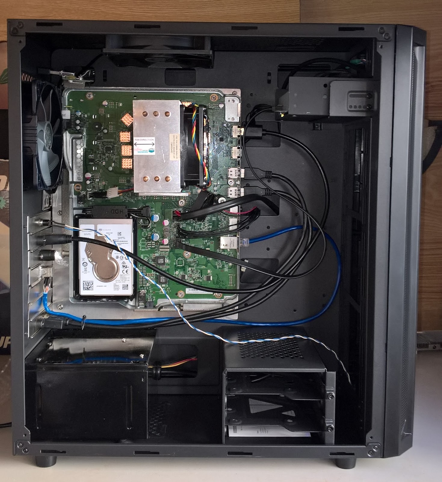
Case:
Although my mod is not locked to an individual PC case I have chosen to use the Deepcool D-Shield V2 as the case for my mod due to it still having a single 5 1/4 inch drive bay.

Case Buttons:
The following picture indicates the pinouts.
XB1X:
To Be Added...
My Wiring.

Closeup.

Sync and USB Board.

Sync Motherboard Alternative.

Sync Button.

XB1S:
Xbox => Colour => PC Case
Power => Green => Power
Eject => Red => Reset
Sync => Yellow => Not Connected
GND=> Black => GND

Case LEDs:
XB1X:
XB1S:
PC Case Rear IO Panel:
I have placed a sticker over a standard PC rear IO plate to hide the PC port holes.

MOD PICS:


WHATS NOT INCLUDED IN THE MOD
Infra-red Receiver.
CLEARANCE ISSUES
XB1X:
1. The front of the XB1X motherboard tray with the wireless controller board must be at least 5mm from the rear edge of the adapter plate to allow space for soldering the power\eject buttons, LEDs, antenna extension cables.
2. The wireless controller board sticks out from the official XB1X motherboard tray by 3-4mm toward the top of the PC case..
3. Mounting to the PC case all of the rear ports mounted on the PCI brackets must be higher than the top of the XB1X motherboard tray. I have designed all of my rear ports with this in mind.
4. The x-clamp height required is 9mm between the APU core top and the motherboard tray.
XB1S:
WHAT I STILL NEED TO KNOW
XB1X:
1. Are there only 5 wireless antennas, 2 on the WiFi board and 3 on the power, Eject, LED aka the Wireless Controller board?
2. The Antennas on the Wireless Controller board are all 3 antennas needed for the wireless controllers or just the largest one?
XB1S:
1. If I want to use custom heatsinks one the XB1S I'll need to make custom x-clamp studs. What are the measurements of the Xbox One S heat pipe version heatsink x-clamp studs? Not the studs on the aluminium heatsink version as I already have those measurements. The x-clamp studs are part of the heatsink base and are not removable. Please measure with a set of callipers for the most accurate results.

2. Is the heat pipe version heatsinks leg base level with the APU core height?

HELP NEEDED
Any help needed will be asked for here.
MENTIONS
Id like to thank the following people for their input.
ozzylow - For giving me the idea to use aluminium motherboard adapter plates for all of my console to PC case mods.
ocean515732 eBay User - For his info and for supplying me with the long drive power cables - Haven't found anywhere else to get these anymore.
ITEMS FOR SALE
ocean515732 eBay User - For his info and for supplying me with the long drive power cables - Haven't found anywhere else to get these anymore.
ITEMS FOR SALE
Current as of the 25/05/21.
V26898-B854-V2 Heatsink - Expression of interest:
I have the opportunity to purchase a lot of about twenty used V26898-B854-V2 Heatsinks. If I have sufficient interest I will purchase and modify them to suite:
PS3 - Fats and Slim - Not supers slims
PS4 - All Versions
Xbox 360 - All versions
Xbox One - All versions
Modifications would include:
Clamping hardware holes drilled
Heatsink legs trimmed or removed depending on the console you require them for.
Price wise I would be looking at about $50 Australian dollars for the modified heatsink. Not including postage to you.
Post a comment if you are interested in a Pre-modified Heatsink.
Current as of the 02/02/20.
No longer needed items that I might be willing to sell. Leave a comment in the replies if your interested.
XB1X\S Prototype Motherboard Adapter Plates
Each $20 each Australian Dollars Plus Shipping.
I have 2 or 3 early XB1X prototype motherboard adapter plates where the XB1X motherboard mounting holes are not in the same location as on the final version master plate. Still completely usable though for a PC case mod. From memory one plate contains the XB1S holes as well.
Either use them for a pc case mod or instead just use them when your working on the motherboard to prevent the motherboard flexing and bending while your working on it.
Pic to be added...
More Updates to follow...