Tuesday, December 5, 2023

ORIGINAL XBOX PC DVD DRIVE MOD - SD-616F / SD-616T / GDR-8163 / GDR-8164

I will be updating this...

This is a tutorial to show you how to perform the cleanest wire installation to allow the following PC DVD drives to be connected to the original Xbox:

  1. Toshiba Samsung SD-616F or SD-616T
  2. LG GDR-8163 or GDR-8164
NOTE: For the rest of the conversion including firmware flashing, Xbox case drive modification and SD-616 drives Internal motor reverse. See the following links:

Links to be added...
  1. Toshiba Samsung SD-616F - Here
  2. Toshiba Samsung SD-616T - Here
  3. LG GDR-8163 or GDR-8164 - Here
DETAILS:
I figured out I can use the 4 pin analogue audio output pins on the rear of the drive to output the four signals required by the Xbox to properly communicate with the drive.

REQUIRED:
  1. Soldering Iron.
  2. Soldering Braid \ Wick.
  3. Small metal cutter \ snips - To cut the pins.
  4. 30awg Kynar Wire
  5. Xbox DVD drive cable - To solder to the connector pins.
  6. IDE power splitter cable - To power the disc and the hard drive at the same time.
  7. Analogue audio end connector with 4 pins - Can be found in old computers with IDE disc drives.


PREPERATION:

SD-616F or SD-616T

Drive Circuit Board Analogue Audio Pins:
  1. Use soldering braid \ wick to remove solder from around the 4 Analogue Audio Pins on the drives circuit board bottom.
  2. On the side of the drive where the pins go through the plastic, remove / de-solder the capacitor from in front of the pins to get access to the drive pins. Don't worry if the pads come off of the circuit board as the capacitor is only for the analogue audio circuit. It won't need to be re-soldered.
  3. Use the metal snips to can the end of the pin legs away so they end up being a few millimetres away from the circuit board. After you have snipped them you may need to gently twist them around till they break away.
  4. Tin the new end of the pins with solder.
  5. Pass the 4 wires through the 4 holes and solder them to the pins.
  6. Route the wires and solder them wires like in the picture below.
Capacitor to remove.


Pins cut.


Pins with wires soldered to them.


Bottom side of the board with the wires going through the old pin holes.


Whole bottom board with wires.


Analogue Audio Cable Connector:
Unless you already have new pins and the crimping tools for this connector type you will need to re-use the pins by doing the following:
  1. Use a needle to remove the pins from connector socket. Push on the tab visible in the hole then pull.
  2. If the pin locking tab bent downward during removal re-bend it at an angle again so that it won't come out when put back in.
  3. Preferably spread, otherwise grind the wire strain reliever so that the wire is no longer being held in place. If you have to grind, grind as least as possible.
  4. Rock the wire back and forth near where the cable wires are crimped in the pin until all of the wire strands break.
  5. Tin the pin with solder on the same side as where the cable strain reliever was above where the wires were crimped inside the pin.
  6. Insert the modified pin back into the cable connector.
NOTE: All of the connectors I've seen only have 3 pins so you will have to take a pin from a 2nd cable connector.

Xbox Disc Dive Wires:
  1. Remove all of the wires from the Xbox 12 pin socket and all but four wires from the 14 pin socket. Use a pin to bend the socket tabs then pull the pin free. See Wire picture below.
  2. Strip and tin a few millimetres off of the end of the Xbox disc drive cable wires.
  3. Place the tinned wire so that it sits over the crimped section of the Analogue Audio pin.
  4. Slide it into the appropriate hole inside of the connector. If it doesn't fit you may have to remove some solder until it does.
Xbox motherboard with dvd power 14 pin socket with connector showing wires to leave in-place.
Pic to be added...

Wednesday, November 8, 2023

Finalman's PS4 Pro and PS5 FAT LED Adapter PCBs

------------WILL GO ON SALE SOON------------

Either through Ebay if your in Australia or order-able through pcbway.com

THE IDEA

These adapter PCBs allow the PS4 Pro and PS5 FAT consoles to change the LED colour by installing a small printed circuit board into the Consoles.

PCB 1 - Blue and White LED Swap:
This printed circuit board swaps the blue and white LEDs. The PS4 Pro and PS5 look better with the blue LED illuminating once the PlayStation has booted rather than the plain old white LED.

NOTE: The orientation it is placed in does not matter.


PCB 2 - Blue, White or Orange LED Swap:
This printed circuit board allows you to swap blue, white and orange LEDs colours around by bridging different solder points.


The solder points are in the 3 groups. .

The top group is for the boot (booting) LED. The middle group is for the idle (booted) LED. The bottom group is for the rest (sleep) LED.

The middle pad in each group is the PS4/PS5 status. It is what you bridge with another pad in that group to change the output colour of the LED

The three pads around the middle pad in each group defines what the output LED colour is. The top pad is for Blue. The Middle pad on the side is for White. The bottom pad is for orange.


Example: Boot = White, Idle = Blue, Rest = Orange (unchanged).

WARNING: Do not get the PCB orientation wrong as you might damage the PlayStation motherboard. The end of the PCB with the White "PS4" and "PS5" text connects to the PlayStation motherboard through the included 5cm ribbon cable. The side with the White "LED" text connects to the PlayStation's LED circuit board through the ribbon cable that came with the PlayStation.

NOTE:  Although you can bridge multiple pads to get different colours in the same group you should avoid doing this.

NOTE: The soldering iron tip should be 0.5mm diameter or less to make the job easier.

NOTE:  For my personnel PS4 Pro and PS5 FAT I have physically replaced the orange LED with a red LED and the white LEDs with a green LEDs.  If you too choose to do this you also need to change the LED resistors.

INSTALLATION:

PS4 Pro:

1. Take off the PS4 Pro bottom housing.
2. Disconnect the LED ribbon cable from the motherboard.


3. Remove the double sided tape cover from the bottom of the LED PCB to expose the sticky surface.
4. Place the PCB in about the same position as in the picture below and connect up the ribbon cables as pictured. The 5cm ribbon cable was included with the PCB. The blue ends of the 5cm ribbon cable are to be both facing up toward you.

Blue and White LED swap PCB installed.

Blue, White and Orange LED swap PCB installed.

PS5 FAT:

Blue and White LED swap PCB installed.

Blue, White and Orange LED swap PCB installed.

FOR SALE:

eBay Australia:
Auction link to be added...

Purchase on pcbway.com:
You will purchase the bare the bare PCB and you will need to separately purchase and solder the two connectors.

You should purchase the PCB with a thickness of 1.0mm.

link to be added...

Parts Required:
  • Two 6 pin 0.5mm pitch clamshell connectors. Cheap and common on eBay and Aliexpress
  • 6 pin 0.5mm 5cm same side contacts ribbon cable


Wednesday, April 5, 2023

Finalman's Sony PlayStation 2 IDE PCB mod

I DO PLAN TO SELL THESE AT SOME POINT

Either through Ebay if your in Australia or order-able through pcbway.com

------------------------------------------------------------

I am designing afew a printed circuit boards to restore hard drive IDE connector on the rear of v12-v13 slim PlayStation 2's.

Will work on all SCPH-700xx model PS2s. Does not work on SCPH-750xx, SCPH-770xx, SCPH-790xx or SCPH-900xx model PS2s.

The advantage of this doing it this way over soldering SATA \ SD to IDE adapters is that if those adapter fail you have to de-solder the 30 plus adapter wires and then replace the adapter or if using maxdiypower's PS2 HD connect and the adapter board fails you cannot replace it because it is now discontinued.

On my IDE adapter boards, SATA / SD hard drive to IDE adapters will be quickly swap-able.

The disc drive will need to be removed from the PS2. Not really a big deal though cause the HDD will be faster and lasers wear out requiring disassembly of the console to replace.

Horizontal Top.

Horizontal Bottom.

Vertical Top.

Vertical Bottom.

PROS:
Faster Load Times
SATA HDD, SD to IDE adapters easily swap-able

CONS:
29 Wires require soldering
Requires Housing Modifications
Requires Chassis Modifications
No disc drive
Cannot mount a screen to the PS2 rear.

FOR SALE - COMING SOON

INCLUDED:
PS2 IDE PCB
Enameled Wire
GND wire
2x 3mm bolts
2x 3mm nuts

TUTORIAL

PREPERATION:

If the two pads in the following picture have solder on them, use a de-soldering braid to remove the solder so that the adapter PCB sits perfectly flat on the PS2 motherboard.


MOUNTING:

With the head of a 3mm bolt facing the floor put it through each of the two holes shown in red in the following picture. Then mount the adapter PCB so that all three of it's and the PS2 motherboard  holes line up. Finally install the 3mm nut onto the bolt and tighten.


SOLDERING

Vertical Adapter PCB:
You solder all of the wires directly to their respective IDE pins except for ground pins, for them you only solder a single ground wire to one of the ground pins.

IDE pin number one is denoted by a rectangular pad. The other IDE pins on that same side of the PCB are all odd number pins going from 1 to 39. The IDE pins on the other side of the PCB are all even number pins going from 2 to 40. The odd and even numbered pins increase the further they get from pin 1.


Horizontal Adapter PCB:
You solder all of the wires directly to their respective IDE pins except for ground pins, for them you only solder a single ground wire to one of the ground pins.

IDE pin number one is denoted by a single solid white circle right next to it. The other IDE pins on that same side of the PCB are all odd number pins going from 1 to 39. The IDE pins on the other side of the PCB are all even number pins going from 2 to 40. The odd and even numbered pins increase the further they get from pin 1.


A white circle around a hole means that a wire must pass through that hole to the other side of the PCB, to be soldered to the closest IDE pin where the wire comes out.


PS2
All credit goes to AUTOMAN for discovering the solder points.

NOTE: Rather than soldering to all 8 GND IDE pins my IDE adapter board only requires you to solder to a single GND pin. Use a thicker insulated wire for this.

CASE MODIFICATIONS:

NOTE: After you have finished the mod and when you go to reassemble the PS2 you need to put a ...mm thick washer where you cut off the metal shielding from both top and the bottom side of the motherboard where any of the 6 housing securing screws goes through.

Top Chassis:
You need to cut along the red line at the end of the plastic shown in the next picture.


Before.

After.

Bottom Chassis:

You can choose to either cut or drill depending on your preference.

Drill - Not Recommended.
You need to enlarge two holes with a 3...mm drill shown as red circles in the next picture. 


Then:
  1. Secure the adapter pcb to PS2 motherboard using nuts and bolts.
  2. Solder the wires.
  3. Remove the nuts and bolts securing the adapter pcb.
  4. Hold the adapter pcb in place.
  5. Secure the, bottom chassis, motherboard and adapter pcb together through the two holes you drilled using nuts and bolts.
After.

Cut - Recommended

You need to cut along the red line shown in the next picture.


Before.

After.

Bottom Housing:
You need to cut along the red line shown in the next picture. Leave the thin plastic middle part that runs length-ways in-place. Try and keep it as square as possible. Use a file once you are done to neaten up the area.


Before.

After.

Disable The Eject Mechanism:
To be added...

3D PRINTED COVER - OPTIONAL
To be added...

Vertical Adapter PCB...


HOW TO MAKE THE HARD DRIVE BOOTABLE

Through the Memory Card:
Install FREEMCBOOT onto a memory card. Then...

With a Modchip:
Install a modchip and set the DEV mode to whatever ELF file you want to boot.

SATA TO IDE HDD ADAPTER

NOTE: The adapter and hdd will require external power to be supplied.

Use an adapter like the one below plugged into the PS2's new ide port.


OR

Use an adapter like the one below with an IDE cable running to the PS2's new ide port.


Tuesday, March 7, 2023

How To Swap Parts Between Different PlayStation 2 Model Revisions

The purpose of this blog is to explain how to modify and swap PS2 parts between different PS2 model revisions that have 8 case housing screws.

This is useful if you have PS2 parts from different model revisions but not enough to make a complete matching parts model PS2.

NOTE: Not including are JAP, US, EU and AU launch model PS2s that have 10 housing screws.

NOTE: ALTHOUGH I HAVE ACCESS TO AFEW DIFFERENT PS2 MODEL REVISIONS I DON'T HAVE ACCESS TO EVERY SINGLE ONE SO THERE IS A POSSIBILITY THAT THERE MAY STILL BE UNLISTED INCOMPATIBILITY ISSUES.

NOTE: PS2 motherboards are paired to specific laser model. If you change your PS2 disc drive the laser within the replacement disc drive might be a different model. If this is the case you must use this homebrew app to pair your PS2 to a different model laser.

BUILDING UP A SCPH-30xxx - SCPH-390xx, GH-015 to GH-022 MOTHERBOARD PS2

NOTE: SCPH-350xx R - SCPH-390xx PS2 All parts should be swap-able without issue.

FRONT PANEL - BUTTONS / LEDs / IR SENSOR

NOTE: IR remote function will be unavailable if you proceed with the listed disc drive swap. 

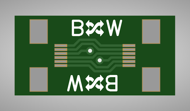
SCPH-50xxx PS2s use a 12 pin 0.5mm pitch connector and SCPH-300xx R - SCPH-390xx PS2s use a 7 pin 1mm pitch connector. I have designed a custom PCB to convert the different connectors to the other kind. I will be selling these if there is anyone interested.


DISC DRIVE

NOTE: You must use the top housing from a SCPH-50xxx because the front panel switches and leds are mounted on the disc drive.

Drive Modification:

NOTE:  If you have and use the top metal chassis with the heat sinks from SCPH-50xxx motherboards you can skip the following modification.

There is a small bit of plastic on the disc drive that needs to be trimmed on SCPH-50xxx PS2 disc drives, otherwise the disc drive will collide with part of the top metal chassis with the heat sinks from SCPH-300xx - SCPH-390xx PS2's . Use a dremel to cut the shape like the in the after picture.

Before.

After.


CHASSIS

Disc Drive Modification:
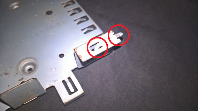
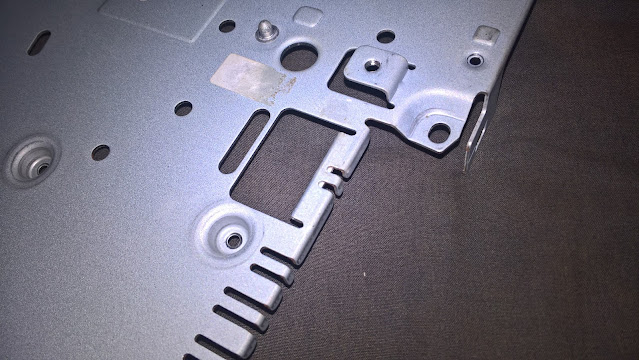
If you use the metal chassis from a SCPH-3xxxx PS2 but the disc drive from a SCPH-5xxxx the bottom chassis rear has a small jut out you need to bend it so that it no longer juts out. Otherwise it will collide with the SCPH-5xxxx disc drive plastic frame.

NOTE: Not all chassis revisions have this jut out.

Before.

After.

USB - Firewire Port Modification:
If you use the metal chassis from a SCPH-50xxx PS2 you need to bend a few tabs on the USB port area.

Before.

After.

Power Supply Modifications:

NOTE: Power supplies from SCPH-50xxx PS2s will not work with SCPH-3xxxx motherboards due to the power connector of SCPH-50xxx PS2s being in a slightly different position.

Connector:
If you use the chassis from a SCPH-50xxx you need to cut off the piece of metal along the edge of the chassis as it will collide with the power connector plastic on 300xx - 390xx PS2 motherboards.

Before.

After.

Standoffs:
If you use the metal chassis from a SCPH-50xxx PS2 but the power supply from a SCPH-300xx R - SCPH-390xx you need to replace the posts it sits on. Use 4x 3mm brass standoffs, 3x Male to Female 20mm long and 1x Female to Female 38.5mm long.


The yellow circle is a different length spacer. You can do either one of two things here:
  1. If you want to avoid drilling part you can use a ...mm female to female standoff and use a 3mm screw to screw through the fan mount plastic, go through the metal chassis and screw into the power supply standoff.
  2. You can drill for a more sturdy power supply mount. To do so you need to prepare the area before you can install the spacer. To do this take a ...mm drill bit and carefully drill the screws thread part of the chassis away. The 3mm hole that goes all of the way through the chassis should be left untouched.
Before.

After.

HOUSING

USB Firewire Sticker:
If you are using the bottom housing from a SCPH-50xxx PS2 you will need to remove the USB port sticker or cut a hole in it for the Firewire port on SCPH-300xx R - SCPH-390xx PS2s.

Power Supply Post:

NOTE: To use a SCPH-50xxx bottom housing you must remove the plastic standoff below where the power supply would be located because it will collide with the power supply.

Before.

After.

BUILDING UP A SCPH-50xxx, GH-023 to GH-029 MOTHERBOARD PS2

BUTTONS / IR SENSOR

NOTE: IR remote function will be unavailable if you proceed with the listed disc drive swap.

SCPH-50xxx PS2s use a 12 pin 0.5mm pitch connector and SCPH-300xx R - SCPH-390xx PS2s use a 7 pin 1mm pitch connector. I am currently designing custom PCBs to convert the different connectors to the other kind. I will be selling these if there is anyone interested.

Pic to be added.

CHASSIS

Top Heat Sink Chassis Swap:

Bottom Chassis Modification:

HOUSING

Bottom Housing Modification: