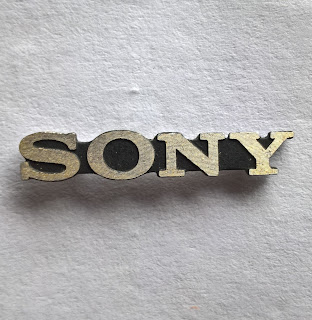
1. Remove the Sony badge from around the Power and Eject buttons. It is held in by double sided tape.
2. Use a few drills and roll them in your fingers to put a hole through the centre black part of the O in the Sony badge. Start with say 2.5mm then go to 3mm.
After...
3. Put the Sony badge back on the PS2 and use a 3mm drill to mark the centre of the O. Then remove the badge and drill all of the way through the PS2 plastic with a 3mm drill.
Before...
After...
4. For best results use a 3mm flat top diffused LED and make the top of it level with the raised letters of the Sony badge text. If the LED has a lip on it around the bottom near the legs use a file and file it down so that it is level with the rest of the LED. Keep the LED legs about 1mm max in length so that the wires won't collide with the power /eject buttons plastic mounting parts.
Round top LED pictured.
5. Feed the LED through the hole with wires and add a resistor. Hot glue the LED in place. Run the LED wires along the case above the disc drive and use sticky tape to tape the LED wires in place. Take note of the path the wire takes and replicate it on your PS2.
PS2 Motherboard:
Pinout:
For all 8 screw PS2 FAT models
See the following Picture:
Orange: Is HDD activity pin. Bottom row 4th pin in.
Red: Square is 5V rail. Circles are 5v pins.
10 screw models.
For 10 screw PS2 FAT models except the launch Japanese models. Solder to the side of the D501 LED and R574 resistor.
NOTE: Use a resistor in the LED wiring.
ALTERNATE - DISC DRIVE LED to HDD LED
Due to the PS2s age resulting disc trays sticking and lasers wearing out you may want to connect the HDD led to the Blue tray status LED. Find the service manual for your motherboard model then find and remove the "0" Ohm resistor on the "TRAY_LED_ON" trace behind the Power/Eject connector on PS2 motherboards GH-010 models and newer. Then solder a wire between the HDD activity pin and the removed resistor solder pad closest to the "TRAY_LED_ON" connector.
DISABLE THE ONBOARD HDD ACTIVITY LED


No comments:
Post a Comment