Wednesday, November 8, 2023

Finalman's PS4 Pro and PS5 FAT LED Adapter PCBs

------------WILL GO ON SALE SOON------------

Either through Ebay if your in Australia or order-able through pcbway.com

THE IDEA

These adapter PCBs allow the PS4 Pro and PS5 FAT consoles to change the LED colour by installing a small printed circuit board into the Consoles.

PCB 1 - Blue and White LED Swap:
This printed circuit board swaps the blue and white LEDs. The PS4 Pro and PS5 look better with the blue LED illuminating once the PlayStation has booted rather than the plain old white LED.

NOTE: The orientation it is placed in does not matter.


PCB 2 - Blue, White or Orange LED Swap:
This printed circuit board allows you to swap blue, white and orange LEDs colours around by bridging different solder points.


The solder points are in the 3 groups. .

The top group is for the boot (booting) LED. The middle group is for the idle (booted) LED. The bottom group is for the rest (sleep) LED.

The middle pad in each group is the PS4/PS5 status. It is what you bridge with another pad in that group to change the output colour of the LED

The three pads around the middle pad in each group defines what the output LED colour is. The top pad is for Blue. The Middle pad on the side is for White. The bottom pad is for orange.


Example: Boot = White, Idle = Blue, Rest = Orange (unchanged).

WARNING: Do not get the PCB orientation wrong as you might damage the PlayStation motherboard. The end of the PCB with the White "PS4" and "PS5" text connects to the PlayStation motherboard through the included 5cm ribbon cable. The side with the White "LED" text connects to the PlayStation's LED circuit board through the ribbon cable that came with the PlayStation.

NOTE:  Although you can bridge multiple pads to get different colours in the same group you should avoid doing this.

NOTE: The soldering iron tip should be 0.5mm diameter or less to make the job easier.

NOTE:  For my personnel PS4 Pro and PS5 FAT I have physically replaced the orange LED with a red LED and the white LEDs with a green LEDs.  If you too choose to do this you also need to change the LED resistors.

INSTALLATION:

PS4 Pro:

1. Take off the PS4 Pro bottom housing.
2. Disconnect the LED ribbon cable from the motherboard.


3. Remove the double sided tape cover from the bottom of the LED PCB to expose the sticky surface.
4. Place the PCB in about the same position as in the picture below and connect up the ribbon cables as pictured. The 5cm ribbon cable was included with the PCB. The blue ends of the 5cm ribbon cable are to be both facing up toward you.

Blue and White LED swap PCB installed.

Blue, White and Orange LED swap PCB installed.

PS5 FAT:

Blue and White LED swap PCB installed.

Blue, White and Orange LED swap PCB installed.

FOR SALE:

eBay Australia:
Auction link to be added...

Purchase on pcbway.com:
You will purchase the bare the bare PCB and you will need to separately purchase and solder the two connectors.

You should purchase the PCB with a thickness of 1.0mm.

link to be added...

Parts Required:
  • Two 6 pin 0.5mm pitch clamshell connectors. Cheap and common on eBay and Aliexpress
  • 6 pin 0.5mm 5cm same side contacts ribbon cable


Tuesday, March 7, 2023

How To Swap Parts Between Different PlayStation 2 Model Revisions

The purpose of this blog is to explain how to modify and swap PS2 parts between different PS2 model revisions that have 8 case housing screws.

This is useful if you have PS2 parts from different model revisions but not enough to make a complete matching parts model PS2.

NOTE: Not including are JAP, US, EU and AU launch model PS2s that have 10 housing screws.

NOTE: ALTHOUGH I HAVE ACCESS TO AFEW DIFFERENT PS2 MODEL REVISIONS I DON'T HAVE ACCESS TO EVERY SINGLE ONE SO THERE IS A POSSIBILITY THAT THERE MAY STILL BE UNLISTED INCOMPATIBILITY ISSUES.

NOTE: PS2 motherboards are paired to specific laser model. If you change your PS2 disc drive the laser within the replacement disc drive might be a different model. If this is the case you must use this homebrew app to pair your PS2 to a different model laser.

BUILDING UP A SCPH-30xxx - SCPH-390xx, GH-015 to GH-022 MOTHERBOARD PS2

NOTE: SCPH-350xx R - SCPH-390xx PS2 All parts should be swap-able without issue.

FRONT PANEL - BUTTONS / LEDs / IR SENSOR

NOTE: IR remote function will be unavailable if you proceed with the listed disc drive swap. 

SCPH-50xxx PS2s use a 12 pin 0.5mm pitch connector and SCPH-300xx R - SCPH-390xx PS2s use a 7 pin 1mm pitch connector. I have designed a custom PCB to convert the different connectors to the other kind. I will be selling these if there is anyone interested.


DISC DRIVE

NOTE: You must use the top housing from a SCPH-50xxx because the front panel switches and leds are mounted on the disc drive.

Drive Modification:

NOTE:  If you have and use the top metal chassis with the heat sinks from SCPH-50xxx motherboards you can skip the following modification.

There is a small bit of plastic on the disc drive that needs to be trimmed on SCPH-50xxx PS2 disc drives, otherwise the disc drive will collide with part of the top metal chassis with the heat sinks from SCPH-300xx - SCPH-390xx PS2's . Use a dremel to cut the shape like the in the after picture.

Before.

After.


CHASSIS

Disc Drive Modification:
If you use the metal chassis from a SCPH-3xxxx PS2 but the disc drive from a SCPH-5xxxx the bottom chassis rear has a small jut out you need to bend it so that it no longer juts out. Otherwise it will collide with the SCPH-5xxxx disc drive plastic frame.

NOTE: Not all chassis revisions have this jut out.

Before.

After.

USB - Firewire Port Modification:
If you use the metal chassis from a SCPH-50xxx PS2 you need to bend a few tabs on the USB port area.

Before.

After.

Power Supply Modifications:

NOTE: Power supplies from SCPH-50xxx PS2s will not work with SCPH-3xxxx motherboards due to the power connector of SCPH-50xxx PS2s being in a slightly different position.

Connector:
If you use the chassis from a SCPH-50xxx you need to cut off the piece of metal along the edge of the chassis as it will collide with the power connector plastic on 300xx - 390xx PS2 motherboards.

Before.

After.

Standoffs:
If you use the metal chassis from a SCPH-50xxx PS2 but the power supply from a SCPH-300xx R - SCPH-390xx you need to replace the posts it sits on. Use 4x 3mm brass standoffs, 3x Male to Female 20mm long and 1x Female to Female 38.5mm long.


The yellow circle is a different length spacer. You can do either one of two things here:
  1. If you want to avoid drilling part you can use a ...mm female to female standoff and use a 3mm screw to screw through the fan mount plastic, go through the metal chassis and screw into the power supply standoff.
  2. You can drill for a more sturdy power supply mount. To do so you need to prepare the area before you can install the spacer. To do this take a ...mm drill bit and carefully drill the screws thread part of the chassis away. The 3mm hole that goes all of the way through the chassis should be left untouched.
Before.

After.

HOUSING

USB Firewire Sticker:
If you are using the bottom housing from a SCPH-50xxx PS2 you will need to remove the USB port sticker or cut a hole in it for the Firewire port on SCPH-300xx R - SCPH-390xx PS2s.

Power Supply Post:

NOTE: To use a SCPH-50xxx bottom housing you must remove the plastic standoff below where the power supply would be located because it will collide with the power supply.

Before.

After.

BUILDING UP A SCPH-50xxx, GH-023 to GH-029 MOTHERBOARD PS2

BUTTONS / IR SENSOR

NOTE: IR remote function will be unavailable if you proceed with the listed disc drive swap.

SCPH-50xxx PS2s use a 12 pin 0.5mm pitch connector and SCPH-300xx R - SCPH-390xx PS2s use a 7 pin 1mm pitch connector. I am currently designing custom PCBs to convert the different connectors to the other kind. I will be selling these if there is anyone interested.

Pic to be added.

CHASSIS

Top Heat Sink Chassis Swap:

Bottom Chassis Modification:

HOUSING

Bottom Housing Modification:

Wednesday, November 2, 2022

Finalman's Sony PlayStation 2 SLIM in a PC Case Mod

 THE IDEA

This mod is to develop a PS2 SLIM motherboard adapter plate and wiring adapters that are able to be transplanted between different PC cases.

NOTE: Will support motherboard revisions GH-032 to GH-035.

REASONS
  1. Use a PS2 motherboard that has no case or missing case parts
  2. Allow the motherboard exposure to more air rather than being in a confined space
  3. Motherboard steel classis's rust and the rust particles fall on to the motherboard and cause shorts.
  4. Easily change the internal motherboard clock battery.
PERCENT COMPLETE

90%


TASKS

Complete:
Create the PS2 motherboard adapter plate
Create the PS2 to PC case On button and LEDs wiring hardware
Create the Processor/s heat sink adapter hardware
Create the fan cable adapter
Create the VRM heat sink hardware
Create the Hard Disk Drive adapter mounting hardware
Adapt the power supply

Not Complete:
Create the Rear IO port adapter

Extras: (Not important so I might do later on)

PS2 MOTHERBOARD


Dimensions:
The PS2 motherboards GH-032 to GH-035 measure about:

Width = 140mm
Length = 205mm

ADAPTER PLATE

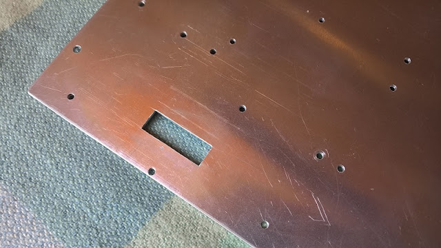
The purpose of the adapter plate is to combine the standoff holes from the PS2 motherboard and PC case onto the one plate.

Details:
The PS2 motherboard is to be mounted onto a custom made ATX aluminium adapter plate measuring 244mm x 244mm x 2mm thick which is the same size as a PC micro ATX motherboard.

Design:
I have designed hardware to work between the the PS2 motherboard and adapter plate.

Orientation:
The PS2 motherboard will be oriented so that the controller and memory card ports will be accessible through the PC case rear IO port area and the rear ports on the PS2 motherboard will be facing toward the front of the PC case.

Orientation.


Procedure:

I used the PS2 and PC motherboards as templates to drill the standoff adapter plate holes depending on the motherboard version. The basic process is as follows:

1. Clean the aluminium plate edges of any burs
2. Clamp the motherboard in place
3. Use a bench drill-press to lightly mark the standoff holes 
using the following drill sizes:

   3.0mm - PS2
   4mm - PC

4. Remove the clamps and motherboard
5. Drill the marked holes all of the way through using the following drill sizes:
    
   2.5mm PS2
   4mm - PC

6. Remove the burs from the drill holes

Example PS2 slim.

HINT: For the most accurate standoff hole locations in the adapter plate get faulty PS2 and PC motherboards. Then grind the motherboard bottom till all of the SMD components and protruding through hole component legs are gone and the motherboard bottom surface is flat. 

WARNING: YOU SHOULD WEAR A FACE MASK TO STOP INHALING PARTICLES THAT MIGHT CAUSE INJURY OR ILLNESS.

Grinded PS2 SLIM motherboard.

Grinded PC motherboard.

PS2 MOTHERBOARD

COOLING:

CPU - GPU - RAM HEATSINK:
I have used a 100x100x3mm thick copper plate and cut it to form the perfect shape for the heat sink base and I then soldered a heat pipe heat sink directly to it. The shape that you see is so that it does not collide with any surface mount components. Will fit both GH-032 and GH-035 motherboards.

Copper Baseplate.

Final heat sink.


NOTE: Due to the location of a voltage regulator module (VRM) on GH-035 motherboards the heatsink base-plate must sit on at least 3mm high standoffs above the motherboard to prevent a collision between the two.

NOTE: To prevent the motherboard bending under the pressure of the thermal pads / putty and stressing the solder joints I will hot glue 10mm (H) x 5mm (W) nylon spacers under the centre of the CPU and GPU.


HEATSINK FAN:
I made the following adapter from a PS2 fan and a PC motherboard fan connector.


MOTHERBOARD VOLTAGE REGULATOR:
I have created a small heat sink to go onto the voltage regulator that normally sinks heat into the motherboards steel chassis. It is basically a 1mm copper plate in an "L" shape to avoid nearby components with a small copper heat sink soldered to it.


NOTE: GH-032 motherboards only have one whereas GH-035 have two voltage regulator chips that require cooling. One of the GH-035 regulators will sink the heat directly into the heatsink base-plate through a thermal pad or thermal putty.

GH-032 location.

GH-035 location.

NOTE: Due to the location of a voltage regulator module (VRM) on GH-035 motherboards the heatsink base-plate must sit on at least 3mm high standoffs above the motherboard to prevent a collision between the two.

PC CASE

Although my mod is not specific to an individual PC case I have chosen to use the....

POWERING:
Will be powered by the PS2 power supply placed inside of a PC power supply. The PS2 power supply has be removed from it's plastic case beforehand.

PORTS

Controllers and Memory Cards:
Accessible through the rear IO port area. To make the ports perfectly centred within the IO port area it will be sitting on ...mm standoffs.

AV:


Optical Audio:
I will be able to use the following Optical adapter to suit. The PCI bracket cut-out was done by myself. This will be attached to one of the PCI slots.


HARD DISK DRIVE:
I designed the following adapter and wired it up to the PS2 motherboard. What you are seeing is the wiring which taps directly into the PS2s onboard IDE/PATA HDD solder points.


 NETWORK:
I have then custom made an Ethernet PCI port bracket. I pulled the RJ45 port from an old laptop, cut the square hole out of a PCI bracket blank and soldered the port to the PCI bracket. I then soldered an Ethernet cable to the RJ45 port pins. This will be attached to one of the PCI slots.


BUTTONS AND LEDS

PS2 Power Button and Power LED to PC Case:
I made the following custom circuit board.


PS2 HDD LED to PC Case:

MEASUREMENTS:

Just some measurements for my memory and also might might help someone else out.
  • Motherboard thickness 1.25mm
  • GPU height above the motherboard on GH-032 motherboards = 2.25mm
  • CPU height above the motherboard on GH-032 motherboards = 1.5mm
Mentions:

ozzylow - For giving me the idea to use aluminium motherboard adapter plates for all of my console to PC case mods.

More to come....

Wednesday, July 6, 2022

PS2 BIOS Chip Swapping

As the blog title says this blog gives info on swapping BIOS chips between different PS2 motherboard revisions.

TOOL:

I didn't want to use a heat gun on the motherboard so I built my own tool to heat up both sides of the BIOS chip legs at the same time. It consists of a broom handle end, two small copper squares, a bolt and a few nuts. I flooded the bios chip legs both sides with solder. Heated my tool on the gas stove then placed my tool on the BIOS chip then dragged it off.


RESULTS

Confirmed Working: 
  1. Putting a BIOS chip from a SCPH-79002 motherboard with a date code of 7D onto a non-FMCB exploitable SCPH-90002 with a date code of 8D to enable FMCB functionality.
  2. Putting a BIOS chip from a SCPH-90002 motherboard with a date code of 8B onto a non-FMCB exploitable SCPH-90002 motherboard with a date code of 0C to enable FMCB functionality.
  3. Putting a BIOS chip from a SCPH-90002 motherboard with a date code of 8D onto SCPH-90002 motherboard with a date code of 8C.
  4. Putting a BIOS chip from a SCPH-90002 motherboard with a date code of 8? onto SCPH-79002 motherboard with a date code of 7C.
Partially Working - With Issues: 
  1. Putting a BIOS chip from a fat SCPH-50002 model GH-026 motherboard onto a slim PS2 SCPH-70002 GH-032 motherboard to enable FHDB functionality on a soldered IDE modded PS2. The PS2 can boot FHDB prepared HDDs without the need of FMCB prepared memory cards. Untested but discs might not be discover-able. See note below.
  2. Putting a BIOS chip from a PAL SCPH-50002 GH-026 motherboard onto NTSC-J SCPH-50000 GH-029 motherboard with a date code of 8C. Changes the language selection options to the PAL ones meaning returns X and O buttons to their common actions, X=enter, O=back. Issue breaks dvd player.
  3. Putting a BIOS chip from a PAL SCPH-70002 GH-032 motherboard onto NTSC-J SCPH-70000 GH-035 motherboard. Changes the language selection options to the PAL ones meaning returns X and O buttons to their common actions, X=enter, O=back. Even though GH-035 motherboards have a few extra voltages due to the combined EE+GS, GH-032 motherboards BIOS still have that data to output those voltages which still allows the PS2 to run.
NOTE: Swapping BIOS chips between different PS2 models may result in discs not reading because of firmware differences between the BIOS and the mechacon IC.

NOTE: Swapping BIOS chips between different region PS2s does not get around the game discs region lock as that is enforced by the firmware inside the mechacon IC.

Not Working:
  1. Putting a BIOS chip from a fat SCPH-50002 model GH-026 motherboard onto a slim PS2 SCPH-70002 with a GH-035 motherboard. Boots to a black screen only
  2. Putting a BIOS chip from a slim SCPH-77002 model GH-051 motherboard onto a slim PS2 SCPH-90002 with a GH-070 motherboard. Boots to a black screen only

Friday, August 13, 2021

Finalman's Sony PlayStation 2 FAT in a PC Case Mod

THE IDEA

This mod is to basically develop a PS2 FAT motherboard adapter plate and wiring adapters that are able to be transplanted between different PC cases.

NOTE: Will support motherboard revisions GH-004 (SCPH-300xx) to GH-029 (SCPH-550xx), except GH-008 (SCPH-180xx)Includes some PS2s models that have 10 case screws and all PS2s that have 8 case screws.

NOTE: Will not support PS2 launch model motherboard revisions GH-001 to GH-003 and GH-008 (SCPH-10xx - SCPH-180xx) due to the HDD being connected through a PCMCIA port. These PS2s have 10 case screws.

REASONS
  1. Use a PS2 motherboard that has no case or missing case parts
  2. Allow the motherboard exposure to more air rather than being in a confined space
  3. Motherboard steel classis's rust and the rust particles fall on to the motherboard and cause shorts.
  4. Easily change the internal motherboard clock battery.
Testing.

PERCENT COMPLETE


90%


TASKS

Complete:
Create the PS2 FAT controller and memory card adapter mounting hardware
Create the USB port adapters
Create the heatsink base plate
Create the PS2 motherboard adapter plate
Create the motherboard bottom VRM heatsink hardware
Create the network adapter mounting hardware
Create the Hard Disk Drive adapter mounting hardware
Create the PS2 to PC case On button and LEDs wiring hardware.
Create the ATX power supply adapter wiring hardware
Create the Processors heat sink adapter hardware.

Not Complete:
Create the port wiring and solder to motherboard.

Extras: (Not important so I might do later on)

PS2 MOTHERBOARD


Dimensions:
The PS2 FAT motherboards GH-010 to GH-029 measure about:

Width = 150mm
Length = 243mm

ADAPTER PLATE

The purpose of the adapter plate is to combine the standoff holes from the PS2 motherboard and PC case onto the one plate.

Details:
The PS2 motherboard is to be mounted onto a custom made ATX aluminium adapter plate measuring 305mm x 245mm x 2mm thick which is the same size as a standard PC ATX motherboard. 

Design:
I have designed hardware to work between the PS2 motherboard and adapter plate depending on either if the ports are left in-place or removed.

NOTE: Motherboard models GH-004 - GH-007 don't require the ports to be removed.

NOTE: Motherboard models GH-010 - GH-029 if the ports are left in-place the motherboard will sit on 35mm high standoffs. This is to provide enough height to so that the ports do not collide with the adapter plate.

NOTE: Motherboard models GH-010 - GH-029 if the ports are removed the motherboard will sit on M2.5 or M3mm, 7mm high standoffs. This is to provide enough height to clear the network adapter hdd power cable on GH-010 to GH-029 motherboards.

Orientation:
The PS2 motherboard will be oriented so that the controller and memory card ports will be accessible through the PC case rear IO port area and the rear ports on the PS2 motherboard will be facing toward the front of the PC case.

GH-004 to GH-007 Motherboards.


GH-010 to GH-029 Motherboards.

Procedure:
I used the PS2 and PC motherboards as templates to drill the standoff adapter plate holes depending on the motherboard version. The basic process is as follows:

1. Clean the aluminium plate edges of any burs
2. Clamp the motherboard in place
3. Use a bench drill-press to lightly mark the standoff holes 
using the following drill sizes:

   2.5mm - PS2
   3.0mm - PS2
   3.5mm - PS2
   4mm - PC

4. Remove the clamps and motherboard
5. Drill the marked holes all of the way through using the following drill sizes:
    
   2.5mm PS2
   3mm - PS2 
   4mm - PC

6. Remove the burs from the drill holes

Example PS2 slim.

HINT: For the most accurate standoff hole locations in the adapter plate get faulty PS2 and PC motherboards. Then grind the motherboard bottom till all of the SMD components and protruding through hole component legs are gone and the motherboard bottom surface is flat.

WARNING: YOU SHOULD WEAR A FACE MASK TO STOP INHALING PARTICLES THAT MIGHT CAUSE INJURY OR ILLNESS.

Grinded PS2 FAT motherboard.

Grinded PC motherboard.

PS2 MOTHERBOARD

COOLING:

CPU - GPU:

GH-004 - GH-007
Due to the configuration of these early PS2 consoles I will be using the original heatsink but mounting a fan on the adapter plate that will blow over the heatsink.

GH-010 - GH-029
I have used a 100x60mmx3mm thick copper plate and cut it to form the perfect shape for the base and I then soldered a heat pipe heat sink directly to it. The shape that you see is so that it does not collide with any surface mount components and will fit on all FAT model PS2s except the launch models.

Copper Baseplate.

If the ports are in place or removed determines the heat sink that can be used. Ports inplace requires the use of a low profile heat sink soldered to the copper base plate due to case width clearance restrictions. Ports removed either a low profile or tower heat sink can be used.

Low profile heat sink.

Tower heat sink without Fan.

NOTE: To prevent the motherboard bending under the pressure of the thermal pads / putty and stressing the solder joints I will hot glue, depending on if the ports are inplace or removed 35mm or 7mm (H) x 5mm (W) nylon spacers under the center of the CPU and GPU.

Pic to be added...

Result:
Ten degrees Celsius lower temperatures than an actual PS2.

RAM:
I will be using small heat sinks on the RAM chips.


MOTHERBOARD VOLTAGE REGULATOR:

GH-004 - GH-005:

Info to be added...

Pic to be added...

GH-015 to GH-029:
Out of all of the PS2 motherboards only GH-015 to GH-029 have a voltage regulator chip that requires cooling. Out of all of those there are only two locations for the voltage regulator chip. Both have been added to my adapter plate to support either location.

GH-015 to GH-023 location.

GH-026 - GH-029 location.

Ports Removed
If the PS2 motherboard has had all of the ports removed and it will be sitting on 7mm high standoffs. I will be using a 3mm thick piece of copper, some thermal paste and pads to sync the heat from the voltage regulator chip into motherboard adapter plate.

Two voltage regulator copper block locations.

Ports In-place
If the PS2 motherboard still has all of the ports it will sit on 35mm high standoffs. I will be using a 2mm thick shaped piece of aluminium, some thermal putty or pads to sync the heat from the voltage regulator chip into piece of aluminium.


PC CASE

Although my mod is not specific to an individual PC case I have chosen to use the....

POWERING:

I soldered wires directly to a PC 20 pin connector that will be connected to the PC power supply motherboard connector. The PS2 expects always-on 12v power so to make the the PC power supply always on I bridged the PWR ON and a GND pins, see here for the workaround section for details.

If the power connector port has been removed I will just solder directly to the motherboard.

If the power port is still there then lugs/crimps will be used to connect to the PS2 power prongs using regular Female Molex connectors the same ones that can be found in the main power supply 20/24 pin, CPU 4/8 pin, PCIe 6/8/12 pin connectors. You have to buy them new unless you have a tool to remove them.


PORTS

Controllers and Memory Cards:
Accessible through the rear IO port area. To make the ports perfectly centered within the IO port area it will be sitting on two 13mm standoffs at the edges and a 19.5mm standoff in the center (not Pictured). A square cut into the adapter plate because otherwise the circuit board on the rear where the ribbon cable attaches would collide with the adapter plate.


Adapter plate hole.

AV:


Optical Audio:
I will be able to use the following Optical adapter to suit. The PCI bracket cut-out was done by myself. This will be attached to one of the PCI slots.


USB:

Ports In-place
I have created USB port to 2.54 header pin adapters out of the USB port from faulty flash drives.


Ports Removed
I will direct solder the USB wires to the motherboard.

HARD DISK DRIVE AND NETWORK:

Ethernet
I have mounted the Ethernet and dial-up port from PS2 network adapter model SCPH-10350 To the adapter plate.

I have then custom made an Ethernet PCI port bracket. I pulled the RJ45 port from an old laptop, cut the square hole out of a PCI bracket blank and soldered the port to the PCI bracket. I then soldered an Ethernet cable to the RJ45 port pins. This will be attached to one of the PCI slots.


Hard Disk Drive
I will be using the Bitfunx PS2 IDE to SATA adapter PCB.


BUTTONS AND LIGHTS:

PS2 Power Button and Power LED to PC Case:

For GH-004 to GH-005 motherboards I designed a 40 pin adapter PCB. For GH-006 to GH-022 motherboards I purchased a few 7 pin adapter pcbs. For GH-23 to GH-029 motherboards I purchased a few 12 pin adapter pcbs.


GH-004 to GH-005 motherboards.
Pic to be added...

GH-006 to GH-022 motherboards.

GH-23 to GH-029 motherboards.

PS2 HDD LED to PC Case:

See here for details.

Mentions:

ozzylow - For giving me the idea to use aluminium motherboard adapter plates for all of my console to PC case mods.

More to come....