This mod is to basically develop PS4 Pro adapter plate, hardware and wiring adapters that are able to be transplanted between different PC cases with no modification to the actual PC case or PS4 motherboard.
REASONS
- Have a bigger style heatsink so that the PS4 APU runs cooler.
- Allow the motherboard exposure to more air rather than being in close proximity to a heated metal chassis.
- Motherboard steel chassis's rust and the rust particles fall on to the motherboard and can cause shorts.
- Easily replace the internal motherboard clock battery.
PERCENT COMPLETE
95%
TASKS
TASKS
Complete:
Create PS4 motherboard adapter plate
Create PS4 motherboard adapter plate
Prepare the APU heat sink
Create custom APU clamping hardware
Create a fan adapter cable
Create ATX power adapter cables
Create BT and WIFI Antenna PCI bracket
Find heat sinks for the APU Voltage Regulators
Find heat sinks for the RAM
Create PS4 to PC case LEDs adaptor
Create PS4 to PC case button adaptor
Build PC case rear IO connector plate
Create the Ethernet PCI bracket
Create custom APU clamping hardware
Create a fan adapter cable
Create ATX power adapter cables
Create BT and WIFI Antenna PCI bracket
Find heat sinks for the APU Voltage Regulators
Find heat sinks for the RAM
Create PS4 to PC case LEDs adaptor
Create PS4 to PC case button adaptor
Build PC case rear IO connector plate
Create the Ethernet PCI bracket
Create the RAM heat sink Plate.
Not Complete:
Build the APU VRM heat sink mount.
Create fixed clamping hardware
Extras: (Not important so I might do later on)
Nickel-plate the RAM heatsink Plate.
PS4 MOTHERBOARD
Details:
The PS4 Pro motherboard measures about 240mm x 270mm and 1.4mm thick.
PS4 MOTHERBOARD
Details:
The PS4 Pro motherboard measures about 240mm x 270mm and 1.4mm thick.
There are currently 3 versions of PS4 Pro motherboard layouts. CUH-70xx that ship with NVA-00x motherboards. CUH-71xx that ship with NVB-00x motherboards. CUH-72xx that ship with NVB-00x motherboards. NVB and NVG motherboard versions have matching mounting hole locations. I will show you the differences in relation to NVA vs NVB\NVG motherboards.
As can be seen in the following pictures there are 4 differences highlighted in red circles. The three lower circles are new mounting holes that were not present on NVA motherboards. The highest red circle on is the standoff hole for NVB/NVG motherboards has been moved about 1mm on the horizontal plane in relation to the picture closer to the APU area. The following pictures show those differences.
PS4 CUH-70xx NVA motherboard pictured.

PS4 CUH-71xx NVB motherboard pictured.

ADAPTER PLATE
Details:
The PS4 motherboard is to be mounted on an aluminium adapter plate measuring 244mm x 270mm (micro-atx motherboard height). The purpose of the adapter plate is to combine the standoff holes from the PS4 motherboard and PC case motherboard standoffs onto the one plate.
PS4 CUH-70xx NVA motherboard pictured.

PS4 CUH-71xx NVB motherboard pictured.
ADAPTER PLATE
Details:
The PS4 motherboard is to be mounted on an aluminium adapter plate measuring 244mm x 270mm (micro-atx motherboard height). The purpose of the adapter plate is to combine the standoff holes from the PS4 motherboard and PC case motherboard standoffs onto the one plate.
Orientation:
The PS4 motherboard will be oriented so that the rear ports will be accessible through the PC case rear IO port area.
The PS4 motherboard will be oriented so that the rear ports will be accessible through the PC case rear IO port area.
Procedure:
I used the PS4 and PC motherboards as templates to drill the standoff adapter plate holes depending on the motherboard version. The basic process is as follows:
1. Clean the aluminium plate edges of any burs
2. Clamp the motherboard in place
3. Use a bench drill-press to lightly mark the standoff holes using the following drill sizes:
I used the PS4 and PC motherboards as templates to drill the standoff adapter plate holes depending on the motherboard version. The basic process is as follows:
1. Clean the aluminium plate edges of any burs
2. Clamp the motherboard in place
3. Use a bench drill-press to lightly mark the standoff holes using the following drill sizes:
PC - 4mm
PS4 - 4mm - The holes around the APU
PS4 - 9/64 - Preferred, Otherwise use 3.5mm - All other mount holes
5. Remove the clamps and motherboard
6. Drill the marked holes all of the way through using the following drill sizes:
PC - 4mm
PS4 - 3mm
7. Remove the burs from the drill holes
Drilling the Heatsink Clamping Hardware Holes:
To make sure the clamping bolts as close to centre as possibly on the aluminium adapter plate you can either:
Option 1 - Recommended
Create a custom spacer 6.5mm wide with a 3mm hole drilled through the centre. Place the spacer in each of the four motherboard clamping hardware through-holes before drilling a 3mm hole through the adapter plate.
NOTE: The 3mm drill hole in the middle of the 6.5mm spacer must be perfectly centred within the spacer.
To make sure the clamping bolts as close to centre as possibly on the aluminium adapter plate you can either:
Option 1 - Recommended
Create a custom spacer 6.5mm wide with a 3mm hole drilled through the centre. Place the spacer in each of the four motherboard clamping hardware through-holes before drilling a 3mm hole through the adapter plate.
NOTE: The 3mm drill hole in the middle of the 6.5mm spacer must be perfectly centred within the spacer.

Option 2 - Not Recommended
With the PS4 motherboard sitting on standoffs the shorter the better use a bench drill and a 6.5mm drill bit it is possible to drill straight down through each of the four motherboard heatsink clamping hardware holes. Use light pressure until the drill leaves a mark you can use a guide to drill all of the way through with a 3mm drill bit.
NOTE: ONLY USE IF you cannot make the spacers listed previously as this method is less accurate.
NOTE: If the drill grabs the motherboard clamping hardware hole it will widen out the hole making the centre mark less accurate.
NOTE: If the drill is bent it may result in out of place centre markings. The higher the standoffs the worse the issue can be.

Motherboard Adapter Plate.


Grinded PC motherboard.


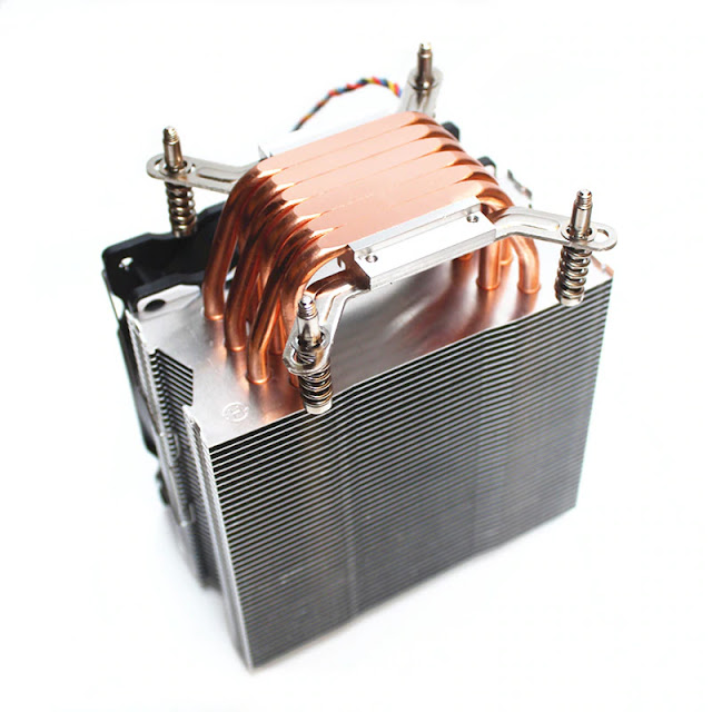
Modified Heatsink with shortened legs.

Motherboard Mounted.
HINT: If using an adapter plate measuring 305mm x 270mm (standard atx motherboard height) for the best results position the PS4 Pro motherboard so that the Ethernet port is directly behind the top PCI slot before drilling the standoff holes.
HINT: For the most accurate standoff hole locations in the adapter plate get faulty PS4 and PC motherboards. Then grind the motherboard bottom till all of the SMD components and protruding through hole component legs are gone and the motherboard bottom surface is flat.
WARNING: YOU SHOULD WEAR A FACE MASK TO STOP INHALING PARTICLES THAT MIGHT CAUSE INJURY OR ILLNESS.
Grinded PS4 Pro motherboard.

Grinded PC motherboard.

COOLING:
APU:
Due to the ability to easily adapt it to the PS4s clamp design I will be using either of the following.
Be Quiet! ShadowRock TF2 - Thanks to Firehuntah in the comments for linking to his project.

Or
Fujitsu-Siemens V26898-B854-V2.
Modified Heatsink with shortened legs.

Or
AliExpress heatsink.

Clamping
I have came up with custom clamping hardware that I can use for heatsink clamping.
For best results preferably buy the X-clamp from CUH-70xx PS4 Pros. Then bore the four holes out with a 1/4 drill. Connect the heat sink to the adapter plate using official x-clamp and created custom height spacers.
Order:
1. 3mm bolt
2. Adapter plate
3. Lower brass spacer. 3mm thread tapped through the centre. Use for all heatsink types. Height given is for 10mm PS4 motherboard standoffs.
2. Adapter plate
3. Lower brass spacer. 3mm thread tapped through the centre. Use for all heatsink types. Height given is for 10mm PS4 motherboard standoffs.
7.5mm (H) x 9mm (W).
4. Upper brass spacer. 3mm hole through the centre. This measurement of spacer is only for flat bottom heatsinks like the Fujitsu-Siemens V26898-B854-V2. Other heatsinks types where the processor contact area is at a different level to the clamping hardware will require a different length spacer.
6.75mm (H) x 6mm (W).
5. PS4 clamp and motherboard backing plate
6. Heat sink base legs / mounting hardware - Not Pictured
7. 3mm nut
Without Clamping hardware.

With clamping hardware.

Without Clamping hardware.

With clamping hardware.
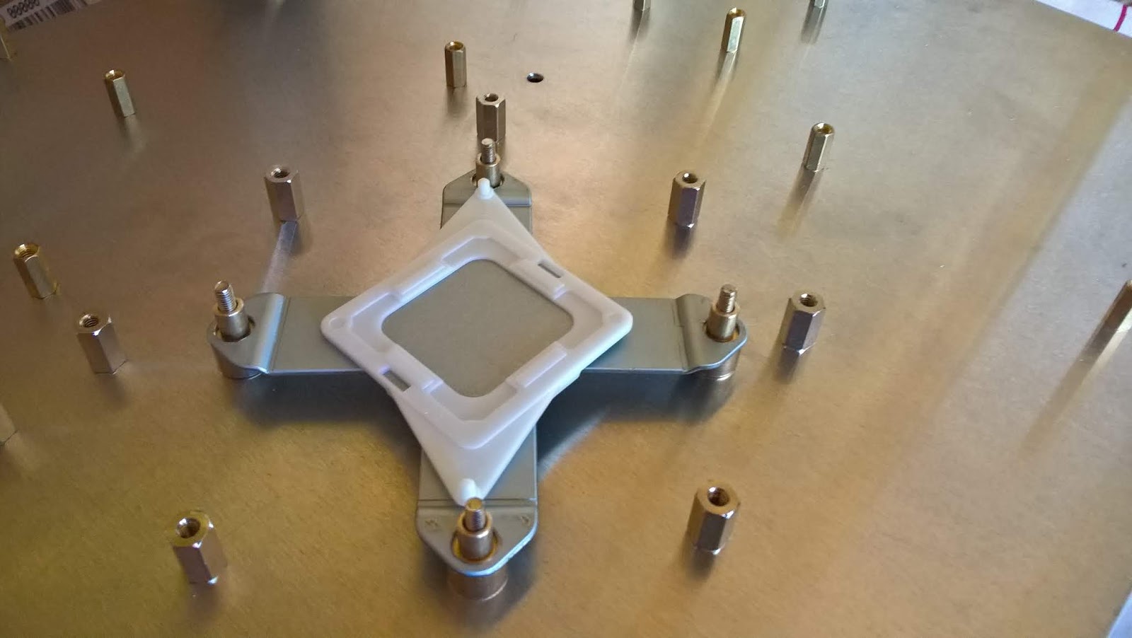
WARNING: Care must be taken when inserting or removing the motherboard as it is more likely to flex when doing so, due to the spring state of the x-clamp. Proper procedure after placing the motherboard is to mount the heatsink. Then tighten the four heatsink nuts. Then screw the motherboard to the other adapter plate standoffs. Removing the motherboard should be done in the reverse order.
Hybrid Clamping:
I have also created hybrid clamping hardware for PS4 Pro using a mix of PS4 Pro and Xbox One FAT clamping hardware. I have done this for a few reasons. Firstly to avoid the other method (Above) which is more complicated due to the spring state of the PS4 x-clamp when securing the motherboard and heatsink. Also so that I can exchange heatsinks between my other Xbox PC case mods.
Parts:
- 4x Xbox One FAT green removeable heatsink. (not all are removable (green are)
- 1x Xbox One FAT x-clamp. Remove the centre plastic piece from it.
- 1x PS4 Pro APU clamp backing plate - Remove the centre metal piece from it. Break off the plastic clips that hold the metal piece in.
- 1x Steel plate - 37.5mm x 37.5mm x 1.5mm - Install the 1.5mm thick metal piece into the PS4 Pro APU clamp backing plate plastic part.
- 4x Brass Spacer - 5mm (H) x 10mm (W) - 2.5mm hole through the centre.
- 4x Brass Spacer - 3mm (H) x 6.5mm (W) - With a 3/16 hole through the centre.
Order:
- 2.5mm bolt ...mm in length
- Adapter plate
- Lower brass spacer - 5mm (H) x 10mm (W) with 2.5mm hole through the centre.
- PS4 Pro motherboard backing plate. Original steel 1mm thick plate piece replaced with same size steel plate but 1.6mm thick.
- Xbox 360 Winchester x-clamp with the centre plastic piece removed.
- Xbox 360 heatsink studs
- Upper brass spacer 3mm (H) x 6.5mm (W) - With a 3/16 (4.75mm) hole through the centre.
- PS4 Pro motherboard
- Heatsink
Fan:
Pinout: Top - Bottom, Same for all PS4 Pro motherboards.
Red - 12v
Black - GND
Blue - PWM (Speed)

I have made up a custom cable to allow the PS4 to run 4 pin PC fans. The PS4 does not have the fan RPM wire that typical PC fans have so I have left that pin unconnected as can be seen in the following picture.

RAM:
In order of preference.
1. Custom RAM Heatsink Plate:
I have decided to make custom RAM heatsink plate. Mine will be 135mm (Front USB to Rear ports) x 130mm x 1mm thick copper plate. I drilled the standoff holes. Marked the outline of the x-clamp and cut the x-clamp shape out of the plate. I will be DIY nickel plating the copper plate.
Mounting order:
- M3 bolt 20mm in length
- Motherboards Adapter Plate
- M3 standoff 6mm in height
- M3 washer 0.5mm in thickness. Used to spread out the compression force on the copper plate.
- Copper RAM heatsink 1mm in height. I now have a 1mm gap between the RAM modules surfaces. 1mm thermal pad or thermal putty will be used to sync them together.
- M3 nut 2.5mm in height.
Total height = 10mm. Same height as the PS4 motherboard standoffs.
RAM copper plate with official clamping hardware.

RAM copper plate with hybrid x-clamp hardware.

Use heat sinks on the RAM chips.

NOTE: Heat sinks mounted with double-sided thermal tape can and do fall off either due to low quality thermal tape and/or poorly cleaned RAM module surface before heat sink attachment.
NOTE: Heat sinks mounted with double-sided thermal tape can and do fall off either due to low quality thermal tape and/or poorly cleaned RAM module surface before heat sink attachment.
3. NVA EMI Shield
NVA motherboards you can use the RAM heat sink \ shield that came with that PS4 version. The RAM heat sink \ shield from NVA motherboards is not compatible with NVB\NVG motherboards due to a moved hole location and collisions with other surface mount components.
Because of the replacement custom clamping hardware I needed to drill 10+ mm (fixed in place way) holes in the RAM heat sink \ shield directly below the clamping bolt heads otherwise the standoffs would collide with the shield.

NVA motherboards you can use the RAM heat sink \ shield that came with that PS4 version. The RAM heat sink \ shield from NVA motherboards is not compatible with NVB\NVG motherboards due to a moved hole location and collisions with other surface mount components.
The thickness of the RAM shield is 0.5mm so that needs to be taken off of the 8 adapter plate standoffs around the APU area to make them the correct height.
Because of the replacement custom clamping hardware I needed to drill 10+ mm (fixed in place way) holes in the RAM heat sink \ shield directly below the clamping bolt heads otherwise the standoffs would collide with the shield.
NOTE: The 5th hole circled on the left side does not need to be modified. I did that earlier before finding out about the collision with components as mentioned above.
NOTE: Not Optimal because the design of the RAM heat sink \ shield traps the heat inside a cavity causing heating of the motherboard which intern raises the temperature of the APU because it is directly above in the center of the RAM chip area. Only use if you have no heat sinks to put on the RAM.
The PS4 motherboard has 6 APU voltage regulators each measuring 6mm x 6mm.
NVA Motherboards:
I'll probably just use Enzotech MOS-C1 heatsinks.

NVB/NVG Motherboards:
Either use Enzotech MOS-C1 heatsinks or use a single heatsink to cover all six six regulators.
To cover all of them with a single heatsink it needs to be at least 70mm in length and no wider then 6mm if using 1mm thermal pads due to surrounding surface mount components. A wider heatsink can be used with 1.5mm thick thermal pads to clear the surrounding surface mount components.
I will be creating a triangle cut-out of aluminium or acrylic (for the see-through look) that attaches to three standoffs that secure to the three motherboard mount holes surrounding the APU VRMs. Then I'll secure the heatsink to the triangle cut-out. The heatsink will then have thermal pad/s or thermal putty to transfer the heat.


NOTE: I am doing it this way as I don't want the heatsink to be able to detach.
Southbridge and Southbridge VRM:
To be added...PC CASE
Although my mod is not specific to an individual PC case I have chosen to use the Deepcool E-Shield or D-Shield.

POWERING:
See my other blog here for instructions on how to power the PS4 with a PC ATX power supply.


Made using a PC IO panel and adding a 1mm thick piece of aluminium with the PS4 rear ports cut out of it. Extremely hard to get it looking perfect so I did the best that I could.

PORTS
Depending on the PC case I will be able to use the following adapters to suit.
USB3 to USB3 PCI bracket.

USB3 Angle adapter.

USB3 to USB3 Pin header.

WiFi/BT:
I have designed a PCB to connect and extend the Wi-Fi antenna cables. Wifi cables will come from the motherboard to the PCB and from the antennas to the PCB. I have done it this way as attaching the Wi-Fi cables to the motherboard while the other end is still connected to the antennas makes it especially difficult connecting them.
I have mounted 3 antennas on a PCI blank bracket using U.FL to RP-SMA pigtails and RP-SMA antennas.


ETHERNET:
I have custom made a Ethernet bracket. I pulled the RJ45 port from an old laptop, cut the square hole out of a PCI bracket blank and soldered the port to the PCI bracket. I then soldered an 80cm Ethernet cable to the RJ45 port pins. This will be attached to one of the PCI slots.


NOTE: If you used an adapter plate measuring 305mm x 270mm the PS4 motherboard should be placed so that the Ethernet port is directly behind the top PCI slot. Cut a hole in a PCI blank bracket in the correct spot to make it look neat and proper.
Without PCI Bracket Blank.

With PCI Bracket Blank.

Without PCI Bracket Blank.
With PCI Bracket Blank.

DISC DRIVE:
Due to the size of the Blu ray drive in the PS4 it is not able to fit into the 5 1/4 inch drive bays. Also the disk drive circuit board is incorporated into the motherboard therefore it does not require the actual disc drive to be attached to launch games and apps unlike the earlier model FAT PS4s that do. It's coming to the end of the PS4s life cycle so I will be using PS4s without the disc drive as my PS4 Pro motherboard is jail-breakable so I no longer need the disc drive.
Stop the unrecognised disc icon from appearing:
Without the disc drive installed to stop the unrecognised disc icon from being shown on the PS4 menu you need to join two pins on the disc eject/detect ribbon cable connector. Do so either using an 8p ribbon cable to adapter PCB or by bridging pins 3 and 4 (3.3v) on the PS4 motherboard.
Motherboard connector pinout:
Pin Function
1 Sensor 1
2 Sensor 2
3 Sensor 3
4 3.3v
5&6 Eject Motor -/+
7&8 Eject Motor -/+
The way that I have done this is put a solder blob between two points on a cut down ribbon cable that I will insert into the PS4 motherboard connector. I have put the ribbon cable in upside down which still works as intended just so that I keep the solder blob from possibly shorting out on the motherboard.
Ribbon cable with solder blob joining the required two points.
BUTTONS:
Power Button:
The PS4 motherboard uses 6 pin 0.5mm pitch ribbon cable headers for these buttons. The two center pins are connected to the power button and the other four pins are GND. I have made the following adapter to suite the PC case buttons.

LIGHTS
The PS4 motherboard uses 6 pin 0.5mm pitch ribbon cable headers for these buttons. The two center pins are connected to the power button and the other four pins are GND. I have made the following adapter to suite the PC case buttons.
LIGHTS
Case LEDs:
The PS4 motherboard connects to LED PCBs through a 6 pin 0.5mm pitch ribbon cable. NVA motherboards use LED-001 PCB and NVB \ NVG motherboards use LED-002 PCB. They appear to be cross compatible with the other. The only difference I have noticed is the LED colour order \ location.
The PS4 case LED PCBs are supplied with 5 volts before going through a resistor. To use the PC case LEDs I need to have resistors on each circuit before the PS4 LED resistor on the PS4 side to protect the PC case LEDs.
The PS4 motherboard connects to LED PCBs through a 6 pin 0.5mm pitch ribbon cable. NVA motherboards use LED-001 PCB and NVB \ NVG motherboards use LED-002 PCB. They appear to be cross compatible with the other. The only difference I have noticed is the LED colour order \ location.
The PS4 case LED PCBs are supplied with 5 volts before going through a resistor. To use the PC case LEDs I need to have resistors on each circuit before the PS4 LED resistor on the PS4 side to protect the PC case LEDs.
PS4 LEDs to PC case LEDs:
- Blue - PS4 Blue LED
- White - PS4 White LED
- Green - Solder a 330 Ohm Resistor to the marked point on the side of the resistor and Connect to PC the front panel Power LED cable. Solder to the other point and connect to the PC front panel Power LED cable.
- Red - Solder a 330 Ohm Resistor to the marked point on the side of the resistor and Connect to the PC front panel HDD LED cable. Solder to the other point and connect to the PC front panel HDD LED cable.
LED-001 Side A PCB.


LED-002 Side A PCB.

PICS:
PS4 PRO: Old MicroATX Case.


CLEARANCE ISSUES
WHAT I STILL NEED TO KNOW
To be added as required.
MENTIONS
Id like to thank the following people for their input.
ozzylow - For giving me the idea to use aluminium motherboard adapter plates for all of my console to PC case mods.
CLEARANCE ISSUES
PS4 Pro:
1. The fan header is the highest object on the bottom of the motherboard at 6mm so you need at least that amount of clearance between motherboard and adapter plate.
2. The ram chips including their solder balls stick out from the motherboard about 1.5mm. Therefore I need to factor in their height as well as the height of the ram heat sinks I intend to use, which will intern give me the standoffs required height dimension.
Working out the heatsink clearance:
The height of the PS4 APU core above the PC case standoffs will be 1.6mm (adapter plate thickness) + 10mm (PS4 motherboard standoffs) + 1.4mm (PS4 motherboard) + 2.4mm (APU Core (H) above motherboard) = 15.4mm.
The height of the Intel CPU IHS top above the PC case standoffs is 1.5mm (PC motherboard) + 8mm (CPU IHS (H) above motherboard) = 9.50mm.
To find out if the chosen heatsink will still fit height wise into the PC case you must subtract 9.50mm (PC CPU core height) from 15.4mm (PS4 APU core height) = 6.4mm the PS4 APU core is higher than PC CPU core height.
Then take 6.4mm off of the PC case CPU heatsink clearance specification to get the maximum height value for the supported case heatsink clearance height specifications and choose a cooler height of that amount or less.
PC Case:
Since m-atx pc motherboards measure 245mm wide but the PS4 pro and adapter plate measure about 270 or so millimetres the PC case must have that extra bit of room at the front of the case. Also requires another few centimetres on top of that if you are going to be using USB angle changer adapters.
MEASUREMENTS
Just some PS4 Pro measurements that might help someone out.
- 2.4mm - Approximate height the APU core is above motherboard
- 2.35mm - Metal plate height for the i-clamp motherboard back plate
WHAT I STILL NEED TO KNOW
To be added as required.
MENTIONS
Id like to thank the following people for their input.
ozzylow - For giving me the idea to use aluminium motherboard adapter plates for all of my console to PC case mods.
ep-game-supply - Over on eBay - For getting me some parts.
JMAGG - Over on YouTube for his information on ribbon cables.
JMAGG - Over on YouTube for his information on ribbon cables.
FOR SALE
More Updates to follow...
