Friday, August 13, 2021

Finalman's Sony PlayStation 2 FAT in a PC Case Mod

THE IDEA

This mod is to basically develop a PS2 FAT motherboard adapter plate and wiring adapters that are able to be transplanted between different PC cases.

NOTE: Will support motherboard revisions GH-004 (SCPH-300xx) to GH-029 (SCPH-550xx), except GH-008 (SCPH-180xx)Includes some PS2s models that have 10 case screws and all PS2s that have 8 case screws.

NOTE: Will not support PS2 launch model motherboard revisions GH-001 to GH-003 and GH-008 (SCPH-10xx - SCPH-180xx) due to the HDD being connected through a PCMCIA port. These PS2s have 10 case screws.

REASONS
  1. Use a PS2 motherboard that has no case or missing case parts
  2. Allow the motherboard exposure to more air rather than being in a confined space
  3. Motherboard steel classis's rust and the rust particles fall on to the motherboard and cause shorts.
  4. Easily change the internal motherboard clock battery.
Testing.

PERCENT COMPLETE


90%


TASKS

Complete:
Create the PS2 FAT controller and memory card adapter mounting hardware
Create the USB port adapters
Create the heatsink base plate
Create the PS2 motherboard adapter plate
Create the motherboard bottom VRM heatsink hardware
Create the network adapter mounting hardware
Create the Hard Disk Drive adapter mounting hardware
Create the PS2 to PC case On button and LEDs wiring hardware.
Create the ATX power supply adapter wiring hardware
Create the Processors heat sink adapter hardware.

Not Complete:
Create the port wiring and solder to motherboard.

Extras: (Not important so I might do later on)

PS2 MOTHERBOARD


Dimensions:
The PS2 FAT motherboards GH-010 to GH-029 measure about:

Width = 150mm
Length = 243mm

ADAPTER PLATE

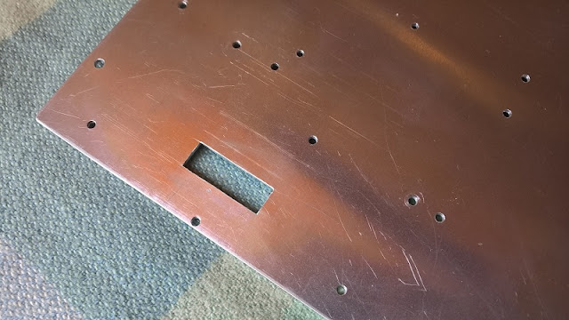
The purpose of the adapter plate is to combine the standoff holes from the PS2 motherboard and PC case onto the one plate.

Details:
The PS2 motherboard is to be mounted onto a custom made ATX aluminium adapter plate measuring 305mm x 245mm x 2mm thick which is the same size as a standard PC ATX motherboard. 

Design:
I have designed hardware to work between the PS2 motherboard and adapter plate depending on either if the ports are left in-place or removed.

NOTE: Motherboard models GH-004 - GH-007 don't require the ports to be removed.

NOTE: Motherboard models GH-010 - GH-029 if the ports are left in-place the motherboard will sit on 35mm high standoffs. This is to provide enough height to so that the ports do not collide with the adapter plate.

NOTE: Motherboard models GH-010 - GH-029 if the ports are removed the motherboard will sit on M2.5 or M3mm, 7mm high standoffs. This is to provide enough height to clear the network adapter hdd power cable on GH-010 to GH-029 motherboards.

Orientation:
The PS2 motherboard will be oriented so that the controller and memory card ports will be accessible through the PC case rear IO port area and the rear ports on the PS2 motherboard will be facing toward the front of the PC case.

GH-004 to GH-007 Motherboards.


GH-010 to GH-029 Motherboards.

Procedure:
I used the PS2 and PC motherboards as templates to drill the standoff adapter plate holes depending on the motherboard version. The basic process is as follows:

1. Clean the aluminium plate edges of any burs
2. Clamp the motherboard in place
3. Use a bench drill-press to lightly mark the standoff holes 
using the following drill sizes:

   2.5mm - PS2
   3.0mm - PS2
   3.5mm - PS2
   4mm - PC

4. Remove the clamps and motherboard
5. Drill the marked holes all of the way through using the following drill sizes:
    
   2.5mm PS2
   3mm - PS2 
   4mm - PC

6. Remove the burs from the drill holes

Example PS2 slim.

HINT: For the most accurate standoff hole locations in the adapter plate get faulty PS2 and PC motherboards. Then grind the motherboard bottom till all of the SMD components and protruding through hole component legs are gone and the motherboard bottom surface is flat.

WARNING: YOU SHOULD WEAR A FACE MASK TO STOP INHALING PARTICLES THAT MIGHT CAUSE INJURY OR ILLNESS.

Grinded PS2 FAT motherboard.

Grinded PC motherboard.

PS2 MOTHERBOARD

COOLING:

CPU - GPU:

GH-004 - GH-007
Due to the configuration of these early PS2 consoles I will be using the original heatsink but mounting a fan on the adapter plate that will blow over the heatsink.

GH-010 - GH-029
I have used a 100x60mmx3mm thick copper plate and cut it to form the perfect shape for the base and I then soldered a heat pipe heat sink directly to it. The shape that you see is so that it does not collide with any surface mount components and will fit on all FAT model PS2s except the launch models.

Copper Baseplate.

If the ports are in place or removed determines the heat sink that can be used. Ports inplace requires the use of a low profile heat sink soldered to the copper base plate due to case width clearance restrictions. Ports removed either a low profile or tower heat sink can be used.

Low profile heat sink.

Tower heat sink without Fan.

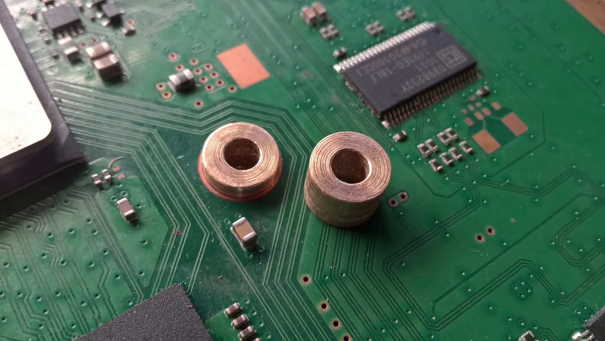
NOTE: To prevent the motherboard bending under the pressure of the thermal pads / putty and stressing the solder joints I will hot glue, depending on if the ports are inplace or removed 35mm or 7mm (H) x 5mm (W) nylon spacers under the center of the CPU and GPU.

Pic to be added...

Result:
Ten degrees Celsius lower temperatures than an actual PS2.

RAM:
I will be using small heat sinks on the RAM chips.


MOTHERBOARD VOLTAGE REGULATOR:

GH-004 - GH-005:

Info to be added...

Pic to be added...

GH-015 to GH-029:
Out of all of the PS2 motherboards only GH-015 to GH-029 have a voltage regulator chip that requires cooling. Out of all of those there are only two locations for the voltage regulator chip. Both have been added to my adapter plate to support either location.

GH-015 to GH-023 location.

GH-026 - GH-029 location.

Ports Removed
If the PS2 motherboard has had all of the ports removed and it will be sitting on 7mm high standoffs. I will be using a 3mm thick piece of copper, some thermal paste and pads to sync the heat from the voltage regulator chip into motherboard adapter plate.

Two voltage regulator copper block locations.

Ports In-place
If the PS2 motherboard still has all of the ports it will sit on 35mm high standoffs. I will be using a 2mm thick shaped piece of aluminium, some thermal putty or pads to sync the heat from the voltage regulator chip into piece of aluminium.


PC CASE

Although my mod is not specific to an individual PC case I have chosen to use the....

POWERING:

I soldered wires directly to a PC 20 pin connector that will be connected to the PC power supply motherboard connector. The PS2 expects always-on 12v power so to make the the PC power supply always on I bridged the PWR ON and a GND pins, see here for the workaround section for details.

If the power connector port has been removed I will just solder directly to the motherboard.

If the power port is still there then lugs/crimps will be used to connect to the PS2 power prongs using regular Female Molex connectors the same ones that can be found in the main power supply 20/24 pin, CPU 4/8 pin, PCIe 6/8/12 pin connectors. You have to buy them new unless you have a tool to remove them.


PORTS

Controllers and Memory Cards:
Accessible through the rear IO port area. To make the ports perfectly centered within the IO port area it will be sitting on two 13mm standoffs at the edges and a 19.5mm standoff in the center (not Pictured). A square cut into the adapter plate because otherwise the circuit board on the rear where the ribbon cable attaches would collide with the adapter plate.


Adapter plate hole.

AV:


Optical Audio:
I will be able to use the following Optical adapter to suit. The PCI bracket cut-out was done by myself. This will be attached to one of the PCI slots.


USB:

Ports In-place
I have created USB port to 2.54 header pin adapters out of the USB port from faulty flash drives.


Ports Removed
I will direct solder the USB wires to the motherboard.

HARD DISK DRIVE AND NETWORK:

Ethernet
I have mounted the Ethernet and dial-up port from PS2 network adapter model SCPH-10350 To the adapter plate.

I have then custom made an Ethernet PCI port bracket. I pulled the RJ45 port from an old laptop, cut the square hole out of a PCI bracket blank and soldered the port to the PCI bracket. I then soldered an Ethernet cable to the RJ45 port pins. This will be attached to one of the PCI slots.


Hard Disk Drive
I will be using the Bitfunx PS2 IDE to SATA adapter PCB.


BUTTONS AND LIGHTS:

PS2 Power Button and Power LED to PC Case:

For GH-004 to GH-005 motherboards I designed a 40 pin adapter PCB. For GH-006 to GH-022 motherboards I purchased a few 7 pin adapter pcbs. For GH-23 to GH-029 motherboards I purchased a few 12 pin adapter pcbs.


GH-004 to GH-005 motherboards.
Pic to be added...

GH-006 to GH-022 motherboards.

GH-23 to GH-029 motherboards.

PS2 HDD LED to PC Case:

See here for details.

Mentions:

ozzylow - For giving me the idea to use aluminium motherboard adapter plates for all of my console to PC case mods.

More to come....

Monday, July 19, 2021

Finalman's Sony PlayStation 2 HDD LED Mod

Sony decided to put the PS2 HDD activity LED inside of the console so I decided to place mine inside the "O" on the Sony badge near the power and eject buttons.

NOTE: The LED will not light up with 3rd party HDD adapters like the GameStar adapter.


Video Below. Sorry for the bad quality but you get the idea.

PREPERATION

PS2 Case:

1. Remove the Sony badge from around the Power and Eject buttons. It is held in by double sided tape.


2. Use a few drills and roll them in your fingers to put a hole through the centre black part of the O in the Sony badge. Start with say 2.5mm then go to 3mm.

After...


NOTE: The Sony badge is a thin piece of aluminium so go slowly and be as accurate as possible as there is no room for error. The thickness of the edges of the O when done will be less than 1mm.

3. Put the Sony badge back on the PS2 and use a 3mm drill to mark the centre of the O. Then remove the badge and drill all of the way through the PS2 plastic with a 3mm drill.

Before...


After...

4. For best results use a 3mm flat top diffused LED and make the top of it level with the raised letters of the Sony badge text. If the LED has a lip on it around the bottom near the legs use a file and file it down so that it is level with the rest of the LED. Keep the LED legs about 1mm max in length so that the wires won't collide with the power /eject buttons plastic mounting parts.

Round top LED pictured.

5. Feed the LED through the hole with wires and add a resistor. Hot glue the LED in place. Run the LED wires along the case above the disc drive and use sticky tape to tape the LED wires in place. Take note of the path the wire takes and replicate it on your PS2.


PS2 Motherboard:

Pinout:

For all 8 screw PS2 FAT models

8 screw models.


See the following Picture:


Orange: Is HDD activity pin. Bottom row 4th pin in.

Red: Square is 5V rail. Circles are 5v pins.

Yellow: Square is 12V rail. Circles are 12v pins.

10 screw models.


For 10 screw PS2 FAT models except the launch Japanese models. Solder to the side of the D501 LED and R574 resistor.

NOTE: Use a resistor in the LED wiring.

ALTERNATE - DISC DRIVE LED to HDD LED

Due to the PS2s age resulting disc trays sticking and lasers wearing out you may want to connect the HDD led to the Blue tray status LED. Find the service manual for your motherboard model then find and remove the "0" Ohm resistor on the "TRAY_LED_ON" trace behind the Power/Eject connector on PS2 motherboards GH-010 models and newer. Then solder a wire between the HDD activity pin and the removed resistor solder pad closest to the "TRAY_LED_ON" connector.

DISABLE THE ONBOARD HDD ACTIVITY LED

Find the service manual for your motherboard model then find and remove the resistor connected to the onboard LED D501 which should be the same name for your models as well. On both of my FAT motherboards the resistor is named R574.


Thursday, July 8, 2021

CONSOLE THERMAL PAD MEASUREMENTS / DIMENSIONS - PS2 / PS3 / PS4 / XBOX / 360 / ONE / SERIES

 PLAYSTATION'S

PS2

FAT

SCPH-30002 

GD-012 - Daughterboard
Quantity: 1
Length: 18mm
Width: 14mm
Thickness: 3mm

GH-005 - Motherboard

IOP
Quantity: 
Length:
Width:
Thickness:

CPU + RAM
Quantity: 1
Length: 70mm
Width: 50mm
Thickness: 1mm

GPU
Quantity: 1
Length: 35mm
Width: 35mm
Thickness: 2mm

Disk Drive Spindle Motor IC - IC700
Quantity: 
Length: 20mm
Width: 10mm
Thickness: 2mm

SLIM

SCPH-700** GH-032-** Motherboard

GPU
Quantity: 1
Length: 35mm
Width: 35mm
Thickness: 0.5mm

CPU
Quantity: 1
Length: 42mm
Width: 42mm
Thickness: 0.5mm

DISC DRIVE IC
Quantity: 1
Length:9 mm
Width: 9mm
Thickness: 2.5mm

VOLTAGE CONVERTER IC
Quantity: 1
Length: 10mm
Width: 6mm
Thickness: 2mm


SCPH-700** GH-035-** Motherboard

GPU/CPU
Quantity: 1
Length: 42mm
Width: 42mm
Thickness: 0.5mm

DISC DRIVE IC
Quantity: 1
Length: 9mm
Width: 9mm
Thickness: 2.5mm

VOLTAGE CONVERTER ICs
Quantity: 2
Length: 10mm
Width: 6mm
Thickness: 2mm


SCPH-750**
Quantity: 
Length:
Width:
Thickness:

SCPH-790**
CPU:
Length:
Width:
Thickness:

SCPH-900**
CPU:
Length:
Width:
Thickness:

PS3

CECHA**, CECHB**, CECHC**, CECHE** - COK-001, COK-002

Southbridge - Red
Quantity: 1
Length: 30mm
Width: 30mm
Thickness: 2mm

PS2 Chip - Blue
Quantity: 1
Length: 30mm
Width: 30mm
Thickness: 1.5mm

Mosfets, Coils - Orange
Quantity: 10
Length: 10mm
Width: 10mm
Thickness: 1.5mm

Under Mosfets - Coils - Yellow
Quantity: 5
Length: 10mm
Width: 5mm
Thickness: 1.5mm


CECH-20** - DYN-001

Southbridge - Red
Quantity: 1
Length: 10mm
Width: 10mm
Thickness: 1.5mm

RSX / GPU Regulators - Blue
Quantity: 1
Length: 8mm
Width: 13mm
Thickness: 1.5mm

CELL / CPU Regulators - Green
Quantity: 2
Length: 10mm
Width: 10mm
Thickness: 1.5mm

Chassis to Blu-ray Drive
Quantity: 1
Length: 10mm
Width: 10mm
Thickness: 1.5mm


CECH-25** - JSD-001 / JTP-001

Mosftet to chassis
Quantity: 2
Length: 
Width: 
Thickness: 

CECH-30** - KTE-001

Coil / Choke to CPU Heatsink - Red
Quantity: 1
Length: 10mm
Width: 10mm
Thickness: 2mm


CECH-42xx

Mosftet to Hestsink Side Chassis
Quantity: 2
Length: 15mm
Width: 8mm
Thickness: 1mm

Motherboard Mosftet Rear to Rear Chassis
Quantity: 2
Length: 15mm
Width: 8mm
Thickness: 1mm

PS4

VRM (Voltage Regulator Modules)

FAT

SLIM

PRO - CUH-70xx / CUH-71xx / CUH-72xx
Quantity: 6
Length: 7mm
Width: 7mm
Thickness: 1mm

RAM:

FAT
Quantity: 8
Length:
Width:
Thickness: ..mm

SLIM
Quantity: 8
Length:
Width:
Thickness: ...mm

PRO - CUH-70xx / CUH-71xx / CUH-72xx
Quantity: 8
Length: 8mm
Width: 8mm
Thickness: 1mm

XBOX'S

XBOX

XBOX 360

XBOX ONE X

SERIES S

SERIES X

XBOX RIBBON CABLES - XBOX / XBOX 360 / XBOX ONE / XBOX SERIES

If you cannot find the exact length get longer just to be safe.


XBOX

XBOX 360

ROL/RF Board:

Xbox 360 E
Pin Count: 14
Orientation: Forward
Pitch: 0.5mm
Length: 170mm

XBOX ONE

XBOX SERIES X

Thursday, March 12, 2020

Finalman's PS3 PC Case Mod

THE IDEA
This mod is to basically develop a PS3 slim model CECH-25xx motherboard adapter plate and wiring adaptors that are able to be transplanted between different PC cases with no modification to the PC case and only a few minor modifications to the PS3 motherboard.

REASONS
  1. Have a bigger style heatsink so that the PS3 CPU and GPU runs cooler.
  2. Allow the motherboard exposure to more air rather than being in close proximity to a heated metal chassis.
  3. Motherboard steel chassis' rust and the rust particles fall on to the motherboard and cause shorts.
  4. Easily change the motherboard clock battery.
PERCENT COMPLETE

100%

TESTING


TASKS

Current:

Complete:
Create the PS3 motherboard adapter plate
Create the custom clamping hardware
Create the ATX power supply adapter wiring hardware
Create the PS3 On/off to PC case wiring adapter.
Create the PS3 LED to PC case wiring adapter.
Create the Processor heatsinks

Not Complete:

Extras: (Not important so I might do later on)

PS3 MOTHERBOARD


The chosen PS3 motherboard will be from CECH-25xx model PS3 slims due to being able to be jailbroken therefore they can play games off of the hard drive. 

Also the disk drive circuit board is incorporated into the motherboard therefore it does not require the actual disc drive to be attached to launch games and apps unlike all earlier model CECHAxx to CECH-21xx PS3s that do.

Dimensions:
The PS3 CECH-25xx model motherboards measure about:

Width=257mm (Including USB port to rear ports)
Height=260mm

ADAPTER PLATE

Details:
The PS3 motherboard is to be mounted onto a custom made ATX aluminium adapter plate measuring 305mm x 250mm x 1.5mm thick. The purpose of the adapter plate is to combine the standoff holes from the PS3 motherboard and PC case onto the one plate.

Orientation:
The motherboard will be oriented so that the USB ports will be accessible through the PC case rear IO port area and the rear ports on the PS3 motherboard will be facing toward the front of the PC case.


Procedure:
I used the PS3 and PC motherboards as templates to drill the standoff adapter plate holes depending on the motherboard version. The basic process is as follows:

1. Clean the aluminium plate edges of any burs
2. Clamp the motherboard in place
3. Use a bench drill-press to lightly mark the standoff holes 
using the following drill sizes:

   3mm - PS3
   3.5mm - PS3
   11/64 4.35mm - PS3
   4mm - PC

4. Drill the PS3 clamping hardware holes - See the text following this section for more info.
5. Remove the clamps and motherboard
6. Drill the marked holes all of the way through using the following drill sizes:
    
   3mm - PS3 
   4mm - PS3/PC

7. Remove the burs from the drill holes

NOTE: For the best results in standard ATX cases position the PS3 motherboard so that the PS3 motherboard top edge sits 10mm lower than the PC motherboard top edge. This is so that one of the PS3 motherboard standoff mounting hole bolts don't collide with a PC standoff screw.

Example PS4.

Motherboard adapter plate.

PS3 motherboard mounted.

Option 1 - Not Recommended
With the PS3 motherboard sitting on standoffs the shorter the better, using a bench drill and a 6.5mm drill bit it is possible to drill straight down through each of the four motherboard clamping hardware through-holes.

NOTE: ONLY USE IF you cannot make the spacers listed in option 2 as this method is less accurate.

NOTE: If the drill grabs the motherboard clamping hardware hole it will widen out the hole making the centre mark less accurate.

NOTE: If the drill is bent it may result in out of place centre markings. The higher the standoffs the worse the issue can be.

Option 2 - Recommended
For the most accurate standoff hole locations in the adapter plate get faulty PS3 and PC motherboards. Then grind the motherboard bottom till all of the SMD components and protruding through hole component legs are gone and the motherboard bottom surface is flat.

WARNING: YOU SHOULD WEAR A FACE MASK TO STOP INHALING PARTICLES THAT MIGHT CAUSE INJURY OR ILLNESS.

Grinded PS3 motherboard.

Grinded PC motherboard.

To make sure the clamping bolts as close to centred as possibly on the aluminium adapter plate you need to create a custom spacer 6.5mm wide with a 3mm hole drilled through the centre. Place the spacer in each of the four motherboard clamping hardware through-holes before drilling a 3mm hole through the adapter plate.

NOTE: The 3mm drill hole in the middle of the 6.5mm spacer must be perfectly centred within the spacer.


COOLING

Processors:

WARNING: Because the processor heatsinks will only be supported at two points if the PC case is dropped or falls it's more then likely the heatsinks will wobble and break one or two corners off of the processor dies thereby killing them.

I have used the GPU heatsink from a CECH-3002 PS3 as a template to cut the perfect heatsink base-plate shape from 3mm thick copper plate. I cut the fins off of the CECH-3002 GPU heatsink leaving only the base-plate. Then I sanded and filed both sides so that they are reasonably flat. I then clamped the CECH-3002 GPU heatsink base-plate to the 3mm copper plate then drilled the two mounting holes and marked the outer base-plate shape. Then bolted the CECH-3002 GPU heatsink base-plate to the other side and once again mark the outer shape. Next I cut, filed and sanded the 3mm copper plate till it matched the CECH-3002 GPU heatsink base-plate shape. I then shortened the overall length of the base-plate so that they don't collide with the four nearby inductors/coils that are grey in colour that can be seen in a picture below. 

Finally I soldered a heat pipe heatsink to it. I have build two of these heatsinks.

Modified CECH-3002 GPU heatsink base-plate. Ready to template.

Final copper base-plates.

Final heatpipe heatsink soldered to base-plate.


NOTE: With the base-plate shape that you see one of the electrolytic capacitors will collide with the CELL/CPU heatsink base-plate. As a simple workaround I will snap-off or de-solder this, move it over slightly and extend the capacitor legs. I prefer this method over modifying the base plates.

Clamping

Connect the heatsink to the adapter plate using official clamps and created custom spacers.

NOTE: On 21xx\25xx model PS3s the IHS's should not be removed as the glue used to attach them is stronger then on previous PS3 models. Attempting to remove them can damage the chips.

IHS's Removeable:

Order:
1. 3mm bolt
2. Adapter plate
3. Inner brass spacer. With centre 3mm threaded hole.

CPU: 14.5mm (H) x 6mm (W)
GPU: 16mm (H) x 6mm (W)

4. Outer brass spacer. With centre 6.3mm (1/4) hole through the centre.

CPU: 7mm (H) x 8mm (W)
GPU: 7mm (H) x 8mm (W)

5. PS3 I-clamp.
6. PS3 I-clamp motherboard backing plate.
7. PS3 motherboard
8. Heat sink base-plate
9. 3mm nut

Without clamping hardware.

With clamping hardware.


IHS's Not Removable:

Order:
1. 2.5mm nut
2. Adapter plate
3. Inner 2.5mm brass standoff.

CPU: 14.5mm (H)
GPU: 16mm (H)

4. Outer brass spacer. With centre 5.5mm (1/4) hole through the centre.

CPU: 7mm (H) x 8mm (W)
GPU: 7mm (H) x 8mm (W)

5. PS3 I-clamp.
6. PS3 I-clamp motherboard backing plate.
7. PS3 motherboard
8. Heat sink base-plate
9. 2.5mm bolt.

Without clamping hardware.

WARNING: Care must be taken when inserting or removing the motherboard as it is more likely to flex when doing so due to the spring state of the I-clamp. Proper procedure after placing the motherboard is to mount the heatsink then tighten the four heatsink screws. Next screw in the rest of the motherboard to adapter plate standoff screws. Removing the motherboard should be done in the reverse order.

Backing Plates:

The metal chassis clamp backing plates have been removed from the chassis and hot glued onto the motherboard.


Fan:

I have made up a custom cable to allow the PS3 to run 4 pin PC fans. The PS3 does not have the fan RPM wire that typical PC fans have so I have left that pin unconnected as can be seen in the following picture.

PS4 Version pictured. PS3 version is wired differently...

Pinout:

Red - 12v
Black - GND
Blue - PWM (Speed)


CPU\GPU VOLTAGE REGULATORS:
More to be added...

RAM:
The PS3 motherboard has two RAM chips each measuring 15mm x 15mm.

More to be added...

Voltage Regulator Modules:
The PS3 motherboard has four voltage regulators each measuring 5mm x 4.8mm that need a heatsink attached.

More to be added...

Southbridge:
The PS3 motherboard southbridge measures 21mm x 21mm.

More to be added...

PC CASE

Although my mod is not specific to an individual PC case I have chosen to use the....

POWERING:
See my other blog here for instructions on how to power the PS3 with a PC ATX power supply.


REAR IO PANEL:
To be added...

PORTS

HDMI
I will be able to use the following HDMI extension adapter to suit. The PCI bracket HDMI cut-out was done by myself. This will be attached to one of the PCI slots.


Optical Audio:
I will be able to use the following Optical adapter to suit. The PCI bracket cut-out was done by myself. This will be attached to one of the PCI slots.


USB:
The USB ports will be accessible through the PC case rear IO port area.

WIFI/BT:
I have mounted 3 antennas on a PCI blank bracket using U.FL to RP-SMA pigtails and RP-SMA antennas.


ETHERNET:
I have custom made a Ethernet bracket. I pulled the RJ45 port from an old laptop, cut the square hole out of a PCI bracket blank and soldered the port to the PCI bracket. I then soldered an 80cm ethernet cable to the RJ45 port pins. This will be attached to one of the PCI slots.


PC CASE FRONT PANEL:

PS3 power button, power LED and HDD LED to PC case front panel wires:

My custom designed PCB. Resistors are 330 Ohm.


PS3 HDD activity LED Mod:
To be added...

Where to solder.
Pic to be added...


PICS:

CLEARANCE ISSUES

Working out the heatsink clearance:
Since the PS3 GPU IHS(Integrated Heat Spreader) top is higher then the PS3 CPU IHS. I will be using it's measurements for my calculations.

The height of the PS3 GPU IHS top above the PC case standoffs will be 1.6mm (adapter plate thickness) + 10mm (PS3 motherboard standoffs) + 1.5mm (PS3 motherboard) + 4.6mm (PS3 GPU IHS top) = 17.7mm.

The height of the Intel CPU IHS top above the PC case standoffs is 1.5mm (PC motherboard) + 8mm (CPU IHS (H) above motherboard) = 9.5mm.

To find out if the chosen heatsink will still fit height wise into the PC case you must subtract 9.5mm (PC CPU core height) from 17.7mm (PS3 GPU IHS top) = 8.2mm the PS3 GPU IHS top is higher than PC CPU core height.

Then take 8.2mm off of the PC case CPU heatsink clearance specification to get the maximum height value for the supported case heatsink clearance height specifications and choose a cooler height of that amount or less.

MEASUREMENTS

Just some CECH-25xx measurements that might help someone out.
  • 4.6mm - GPU IHS top height above motherboard
  • 3.15mm - CPU IHS top height above motherboard
  • 1.45mm - Difference between the IHS top levels
  • 2.25mm - GPU IHS thickness between the core and the IHS Top
  • 1.55mm - CPU IHS thickness between the core and the IHS Top
WHAT I STILL NEED TO KNOW

To be added as required.

MENTIONS

Id like to thank the following people for their input.

ozzylow - For giving me the idea to use aluminium motherboard adapter plates for all of my console to PC case mods.


FOR SALE

More Updates to follow...